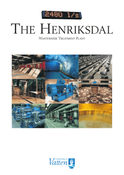
SAMRA WASTEWATER TREATMENT PLANT
DEGREMONT_SAMRA_PLAQUETTE:Layout 1
11/08/08
17:35
Page 1
RÉF. R-ER-020-EN-0808 RÉALISATION : LES ÉDITIONS STRATÉGIQUES - 08/2008
SAMRA
WASTEWATER
TREATMENT
PLANT
JORDAN
DEGREMONT_SAMRA_PLAQUETTE:Layout 1
11/08/08
17:35
Page 2
SAMRA WASTEWATER TREATMENT PLANT JORDAN
PROJECT
OVERVIEW
THE WASTEWATER
MANAGEMENT
SYSTEM FOR THE
GREATER AMMAN
AREA INCLUDES
THE COLLECTION,
CONVEYANCE AND
TREATMENT OF
THE WASTEWATER
GENERATED IN THE
AMMAN RUSSEIFA–ZARQA
BASIN, WHERE 60%
OF THE POPULATION
OF JORDAN LIVE.
Samra wastewater treatment
plant project is:
• a public private partnership (ppp)
for financing the construction and
operation of a public infrastructure
in Jordan based on a Build Operate
Transfer approach over a period
of 25 years.
• the first (BOT) project in Jordan.
• the first (BOT) project by USAID.
• a crucial element in its social,
environmental and economical
development.
The Swedish International
Development Agency (SIDA) financed
the technical assistance during
the preparation phase, construction,
commissioning and 18 months of
the commercial operation period
of the project.
The consulting company is SWECO.
PROJECT FINANCING
169 MILLIONS USD
This is the Project budget financed
by the following partners:
78
USAID
60
BANK CONSORTIUM
SAMRA PLANT CONSORTIUM
(Suez Environnement,
Infilco Degremont Inc. & The Morganti group)
GOVERNMENT OF JORDAN - MWI
17
14
PROJECT
CHARACTERISTICS
• Provides a state of the art
of wastewater treatment.
• Replaces an overloaded waste
stabilization pond treatment
system.
• Produces an effluent with a
quality meeting the Jordanian
Standards.
• Allows safe reuse of treated
water for agriculture.
• Eliminates offensive odors in
the surrounding area.
• Will develop the production of
compost and fodder from the
digested sludge.
• Use the biogas produced in the
sludge digesters to generate
thermal and electrical power.
• Use the hydraulic potential
energy at the inlet and outlet of
the plant to produce electricity.
DEGREMONT_SAMRA_PLAQUETTE:Layout 1
11/08/08
17:35
Page 3
DESIGN
FIGURES
PHASE 1 DESIGN PARAMETERS
2
phases were planned
for this project.
The actual plant
design and construction
is for the first stage
(2015), making provision
for its expansion
to the second phase (2025).
PARAMETER
PHASE 1
PHASE 2
2.27
3.3
267,000
420,000
Population in Millions
3
Dry Weather Flow m /d
Flow / inh. Liters/day
118
127
RAW WATER QUALITY
BOD5
652 mg/l
Grease
30 m3/d
COD
1,449 mg/l
H2S
40 mg/l
TSS
551 mg/l
Nematodes
5 eggs/l
VSS
440 mg/l
F- Coliforms
10 8 MPN/100 ml
TN
130 mg/l
EFFLUENT WATER & SLUDGE QUALITY
BOD5
30 mg/l
F-Coliforms
< 1000 MPN/100ml
TSS
30 mg/l
Nematode Eggs
< 1 egg/l
TN
30 mg/l
Fat, Oil & Grease
< 8 mg/l
pH
6-9
Dry Solids
30%
DO
> 2 mg/l
PROCESS DESCRIPTION
RAW WATER FROM AIN GHAZAL PRETREATMENT FACILITY FLOWS THROUGH A Ø1,500 mm
PIPE INTO TWO PELTON TURBINES IN THE INLET STRUCTURE WHERE ELECTRICAL POWER
IS GENERATED.THE NET HEAD BETWEEN AIN GHAZAL AND SAMRA IS AROUND 78 m.
The outlet joins the incoming
wastewater from Zarqa and
Hashimiyya pumping
stations and distributed into
two grit and sulfide removal
tanks each divided into two
chambers:
• A Grit Removal tank
(19.6m x 13.0 m) with a
volume of 1,560 m3 and an
average hydraulic residence
time (HRT) of 17 minutes. Air
is introduced at the bottom
of the grit chamber causing
heavy particles to settle and
is collected by a screw and
discharged into the grit
classifier. Air bubbles will
cause oil, grease and scum
to float on the surface. It is
then collected in a scum pit
and pumped to the digesters.
• A Sulfide Removal tank
consisting of 2 aerated zones
inseries each of capacity
2,500 m3. Ferric Chloride is
injected here as a catalyst for
the sulfide removal.
The effluent from the sulfide
removal tanks is distributed
into four primary settling
tanks each is 67 m long and
25 m wide. These tanks
remove about 65% of the
total suspended solids and
40% of the BOD5.
The oil and grease are
skimmed and collected in
the scum chamber.
The settled water from the
primary settling tanks is
distributed into eight
biological reactors each of a
total volume of 26,200 m3
consisting of three zones:
• Anoxic zone for exogenous
denitrification (V= 6,875 m3)
• Oxic zone where air is
introduced continuously
through air diffusers to
remove BOD5 and initiate
nitrification (V= 10,825 m3)
• Endogenous zone where air
is introduced intermittently
for complete nitrification
(V= 8,500 m3).
The effluent of the activated
sludge process is distributed
into eight secondary clarifiers
each of Diameter 54 m.
Bio suspended solids are
separated and the settled
sludge thickened and
returned to the anoxic zone
of the aeration tanks.
The clarified effluent of
the secondary settling tanks
flows to two plug flow
chlorine contact basins each
of a volume of 3,500 m3
where it will be in contact
with chlorine for about
35 minutes for its final
disinfection meeting
the Jordanian Standards
893/1995.
DEGREMONT_SAMRA_PLAQUETTE:Layout 1
11/08/08
17:35
Page 4
SAMRA WASTEWATER TREATMENT PLANT JORDAN
SLUDGE
TREATMENT
Primary sludge from the primary settling tanks is thickened
in three covered circular thickeners each of diameter 23 m.
Biological sludge from the aeration tanks is thickened in
another three covered Dissolved Air Flotation units (DAF)
of diameter 18 m.
The two are mixed together in a covered tank of 98 m3
volume before it is pumped to four anaerobic digesters
each of capacity 15,900 m3.
BIOGAS TREATMENT
The Biogas produced in the digesters is stored in two gas
holders each of 5,000 m3 capacity. It undergoes H2S removal
before being used in five Biogas engine generator sets for
the production of electricity.
From Ain Ghazal
Ø1500
3
2.5 m /s
Pelton
Turbines
3
2.5 m /s
General Odour Control
System
From Zarqa
Ø1200
From Hashemiyya
2 x Ø500
FeCl3
Na OH
Biogas
Desulfurization
Desulfurization Odour
Control Units
Scum
Sulfide Removal
The digested Sludge flows to the digested sludge storage
tank where it is pumped to 25 solar evaporation basins
where it is dried to about 30% dry solids.
Lime will be used if necessary for sludge stabilization.
Waste Gas
Burners
From Hashemiyya
2 x Ø500
The sludge is kept in the digesters for three weeks at 35ºC
where it is mixed thoroughly by the Cannon®Mixers using
the recycled compressed biogas.
Heating of the recycled sludge is done by hot water
recovered from the cooling of the engines in a shell-Tube
heat exchanger.
Biogas
Holders
From Zarqa
Ø1200
Grease
Separation
Grit
Gas Power
Generation
Units
Air
Air
Grit & Sulfide Removal Units
Scum
Digesters
Primary Settling Tanks
35°C
Primary
Sludge Thickeners
Scum
Primary Sludge
Thickener
Mixing
Tank
Boilers
Sludge Recycle
Sludge Recycle
Aeration Tanks
Zone 1
Anoxic
Zone 2
Oxic
Exogenous
BOD Removal
Endogenous
De-Nitrification
De-Nitrification
De-Nitrification
2
The plant is designed to ensure that no odor
nuisance occurs at the site boundary. Odors
are extracted in different places of the plant
preventing the emission of unpleasant smells,
providing satisfactory working conditions.
Air
11
Dissolved Activated
Sludge
Flotation units
Sludge Tank
Solar Evaporators
Air
POWER PRODUCTION
PeltonTurbines
Francis Turbines
Biogas Power Generator
Secondary Clarifiers
1.710 MW
1.640 MW
5.375 MW
------------------
TOTAL
8.725 MW
Francis
Turbines
Cl2
Cl2
Chlorination
To Wadi Dhuleil
The process consists of treating polluted air
in a scrubber system containing a special inert
medium, the Biolite in which naturally present
bacteria are fixed. Water is pulverized
periodically on top of it absorbing the
polluting gases.
The treated air in the lower part of the
scrubber is collected and discharged
to the atmosphere.
DEGRÉMONT JORDAN
DAOUD KHOURY
57, BAONIAH STREET JEBEL WEIBDEH - AMMAN - JORDAN
MOBILE : 00 962 795 50 45 77
DAOUD.KHOURY@INFILCODEGREMONT.COM
DHKHOURY@GO.COM.JO
PROJECT
KEY FIGURES
Total Concrete Poured
98,500 m3
Concrete-reinforcing steel
12,500 Tons
Total Length of Electrical Cables
487 Km
Installed Electrical Power
14 MW
Stainless Steel Pipes
600 Tons
Carbon Steel Pipes
180 Tons
Underground GRP Pipes
15.4 Km
Other Pipes (Galvanized,PVC,HDPE)
14.2 Km
Peak Labor Force on site
1950
O&M Labor Force
150
RÉF. R-ER-020-EN-0808 RÉALISATION : LES ÉDITIONS STRATÉGIQUES - 08/2008
ODOR
CONTROL
3
Zone 3
Endogenous
© Copyright 2025


