
OWNER’S MANUAL 1.0
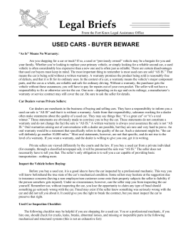
OWNER’S MANUAL 1.0
US OFFICE • 416.845.0132
580 Eccles Ave S. San Francisco, CA. USA. 94080
CANADIAN OFFICE • 403. 452.6004
511 36 Ave SE. Calgary, AB. Canada. T2G1W5
TABLE OF CONTENTS
PK Sound Loves you
2
Safety Precautions
3
Declaration of Conformity
4
5
CSA Compliance Notice
Installation
6
Precautions Regarding Installation Location 6
Mounting or Suspending Loudspeaker
7
Care and Cleaning
8
Operation
9
AC Power
9
System Power Sequencing 9
Operating Temperature
9
Input Connection Plate
10
Some Notes Regarding Cardioid Sub Arrangements
12
Warranty
13
Specifications
14
Accessories
15
| OWNER’S MANUAL 1.0
WWW.PKSOUND.CA
PK SOUND LOVES YOU
Thank you for choosing the Klarity series of professional powered loudspeakers
built by PK Sound. Congratulations, you are now the owner of some of the finest
professional powered loudspeakers on the planet. These cabinets are the culmination
of significant research & development into loudspeaker design and we are confident
that they will provide you many years of reliable use.
Please take the time to go over this owner’s manual so you can understand all
the features built into your Klarity loudspeaker and fully utilize their performance
capabilities.
We stand behind our products so if you have any problems or questions, please get
in touch with support at PK Sound (support@pksound.ca) and we will take care of
you, our valued customers.
KLARITY 8 KLARITY 12 KLARITY 18 KLARITY 218
| OWNER’S MANUAL 1.0
2
WWW.PKSOUND.CA
SAFETY PRECAUTIONS
IMPORTANT SAFETY INSTRUCTION
Read these instructions • Keep these instructions
Heed all warnings • Follow all instructions
CAUTION: To reduce the risk of electric shock, do not remove the amplifier. No user-serviceable parts
inside. Refer servicing to qualified service personnel.
WARNING: To prevent fire or electric shock, do not expose this equipment to rain or moisture. Do not use
this apparatus near water.
SAFEGUARDS: Electrical energy can perform many useful functions. This loudspeaker has been engineered
and manufactured to assure your personal safety. Improper use can result in potential electrical
shock or fire hazards. In order to maintain the safeguards, observe the following instructions for
its installation, use and servicing:
•
This device must be powered exclusively by earth connected (ground) mains sockets in electrical
distribution networks compliant to federal, and provincial/state standards.
•
Before powering the loudspeaker, verify that the amplifier is supplied with the correct, rated Voltage.
•
Verify that the AC power mains connection is capable of satisfying the power ratings of this device.
•
Do not spill water or other liquids into, or on, the unit.
•
Do not use this unit if the Electrical power cord is frayed or damaged. Contact PK Sound or your
dealer for a replacement.
•
Do not defeat the third grounding prong on the grounding type plug. It is provided for your safety.
If the plug does not fit into your receptacle, consult an electrician.
•
Protect the power cord from being walked on or pinched, particularly at the plug and where the
cable exits the loudspeaker at the powerCON connecter.
•
Do not cover the amplifier heat sink. The performance may be affected.
•
Do not install near any heat sources such as radiators, heat registers, stoves or other devices that
produce heat.
•
When flying or suspending the cabinet, use only the attachment points and accessories specified by
PK Sound.
•
Do not use in high moisture environments, humidity and moisture can damage the speaker cones
and surrounds and over time, can cause corrosion on electrical contacts.
•
All repairs & service must be performed by a certified PK Sound repair technician.
| OWNER’S MANUAL 1.0
3
WWW.PKSOUND.CA
DECLARATION OF CONFORMITY
The Klarity 8 and 12 have been tested and found to comply by notified body (DIRECTIVE 2004/108/EEC-EMC)
pursuant to the product family standard for audio professional use:
EN 55103-1 and EN 55103-2 standard (with the limits for E1 and E2 electromagnetic environment); EN61000– 3
– 2, EN61000– 3 – 3
This is a Class B product. In a domestic environment this product may cause radio interference in which case the
user may be required to take adequate measures.
This equipment has been tested and found to comply by Notified Body (DIRECTIVE 2006/95/EEC L.V) pursuant
to the audio apparatus safety requirements: Standard EN 60065.
The Klarity subwoofers (18, 218) have been tested and found to comply by Competent Body (Directive 89/336/
EEC-EMC) pursuant to the product family standard for audio professional use:
EN 55103-1 and EN 55103-2 standard (with the limits for E1 and E2 electromagnetic environment); EN61000– 3 – 2,
EN 61000 – 3 – 3
This is a Class B product. In a domestic environment this product may cause radio interferences in which case the
user may be required to take adequate measures.
This equipment has been tested and found to comply by Notified Body 0715 (Directive 73/23/EEC L.V) pursuant
to the audio apparatus safety requirements: Standard EN 60065.
These limits are designed to provide reasonable protection against harmful interference in a residential situation.
This equipment generates, uses and can radiate electromagnetic energy and, if not installed and used in accordance
with the instructions, may cause interference to radio communications. However, there is no guarantee that
interference will not occur in a particular installation. If this loudspeaker does cause harmful interference to radio
or television signals, which can be determined by turning the loudspeaker off and on, the user is encouraged to
try to correct the interference by increasing the separation between the loudspeaker and the equipment. See
Installation section for more information.
| OWNER’S MANUAL 1.0
4
WWW.PKSOUND.CA
CSA COMPLIANCE NOTICE
CSA CERTIFICATION OF
COMPLIANCE NUMBER 2361014
CSA certification applies to amplifier module only
CSA certified to operate only at 120 Vac in Canada
Certified to CAN/CSA-C22.2 No 60065-03
ANSI/UL 60065-2007
The products listed below are eligible to bear the
CSA Mark shown with adjacent indicator ‘C’, ‘US’
MODEL
RATED
Klarity 8
115V, 50-60 Hz, 2.6 A
Klarity 12
115V, 50-60 Hz, 2.6 A
CSA CERTIFICATION OF
COMPLIANCE NUMBER 1807695
CSA certification applies to amplifier module only
CSA certified to operate only at 120 Vac in Canada
Certified to CAN/CSA-C22.2 No 60065-03
ANSI/UL 60065-2007
The products listed below are eligible to bear the
CSA Mark shown with adjacent indicator ‘C’, ‘US’
MODEL
RATED
Klarity 18
115V, 50-60Hz, 2.6A
Klarity 218
115V, 50-60 Hz, 5.5A
| OWNER’S MANUAL 1.0
5
WWW.PKSOUND.CA
INSTALLATION
Each Klarity mid/high frequency cabinet is designed to sit on the ground, stage, top of a subwoofer enclosure, be
suspended or pole mounted on a 35 mm diameter loudspeaker support pole or tripod speaker stand.
The subwoofer cabinets are designed to sit on a floor, stage, or stacked upon one another. When stacking, lock
them together by mating the small slots on the top of the bottom cabinet with the rubber feet of the cabinet
above it. There is an option available when ordering the Klarity 18 sub to have dedicated rigging points installed
so that it may be suspended.
PRECAUTIONS REGARDING INSTALLATION LOCATION
The Klarity series of loudspeakers are not intended for use in high moisture environments. Install the loudspeaker
in a ventilated area where it will not be directly exposed to high temperature or humidity. Moisture can damage
the speaker cones and surround and over time, can cause corrosion of electrical contacts and metal parts.
Do not install the amplifier in a location that is exposed to direct rays of the sun, or near to hot appliances or
radiators. Placing and using the loudspeaker for long periods on heat-generating sources will affect performance
and can adversely affect the operation and internal components. Keep loudspeakers out of extended or intense
direct sunlight. The speaker driver suspension can permanently dry out and finished surfaces may be degraded
by long term exposure to ultra-violet (UV) light. Installation of the loudspeaker in a damp or dusty environment
may result in malfunction or accident.
The Klarity family of speakers can generate significant kinetic energy due to its acoustical output. When placed
on a slippery surface, the speaker may move. Precautions should be taken so that the speaker does not fall.
Install this loudspeaker as far as possible from radio tuners and TV sets. A loudspeaker installed in close proximity to
such equipment may cause noise or degradation of the picture. If this equipment does cause harmful interference
to radio signal or television picture, which can be determined by turning the equipment off and on, the user is
encouraged to try to correct the interference by one or more measures:
•
Reorient or relocate the receiving antenna.
•
Increase the separation between the loudspeaker and the receiver or television.
•
Connect the equipment into an outlet on a circuit different from that to which the receiver is connected.
•
Consult the dealer or an experienced radio/television technician for help.
| OWNER’S MANUAL 1.0
6
WWW.PKSOUND.CA
Top
Top
Bottom
Rigging Points
Rigging Points
Sides
Sides
Klarity 8
Top
Klarity 12
Top
Back
Bottom
Rigging Points
Safety Points
Rigging Points
Sides
Klarity 18S
Sides
Back
Klarity 215
FIGURE 1: Rigging Points on Klarity Cabinets
MOUNTING OR SUSPENDING LOUDSPEAKERS
DANGER: Mounting or overhead suspension of any heavy load can result in serious injury when not done
correctly. This work should be done by qualified persons following safe rigging practices in accordance with, and
in compliance with, all federal and local regulations governing such work.
WARNING: Never attempt to suspend the cabinets by their handles, use the rigging points only. See the figures
above for the proper rigging points in each cabinet. Contact PK Sound, or see your dealer for the appropriate
rigging kit for your cabinet. Consult a professional rigger or structural engineer prior to suspending loudspeakers
from a structure. You must know the working load limits and determine the mounting or suspension method that
meets static, dynamic, and shock load requirements.
CAUTION: The user assumes all responsibility and liability for the proper design, installation and use of any
rigging or mounting system for Klarity loudspeakers. Please note that only one cabinet can be suspended from
the rigging points, no additional cabinets may be suspended beneath it.
| OWNER’S MANUAL 1.0
7
WWW.PKSOUND.CA
CARE AND CLEANING
The Klarity family of loudspeakers is coated with a tour-proven, thick Poly-Eura
coating. It may be cleaned with a mild soapy damp microfiber cloth and wiped
down finally with a dry cloth.
To reduce the risk of electrical shock, ensure the system in unplugged from AC
power before cleaning. To clean, dust off the speaker cone, you can use a can of
compressed air such as commercial air dusters. Do not blow dust into the horn flare,
it may damage the high frequency compression driver.
| OWNER’S MANUAL 1.0
8
WWW.PKSOUND.CA
OPERATION
AC POWER
The Klarity family of loudspeakers use Neutrik’s
PowerCON connectors for AC power connection. The
powerCON is a locking AC equipment connector with
contacts for line, neutral, and a pre-mating ground
contact. It replaces the standard IEC AC power
connector with a very rugged solution in combination
with a locking device to guarantee a safe and reliable
power connection. The locking tab prevents the AC
power from accidently becoming disconnected. The
grey colored receptacle can be used as a power out
connection to daisy chain to another Klarity series
cabinet. To connect, match the keyways with the
receptacle, push it all the way in and twist until you
hear the locking “click,” letting you know that the
connecter is mated to the receptacle. Similarly, to
disconnect, pull the locking tab towards you, twist and
pull until the connecter is out of its receptacle.
Before plugging in the Klarity speaker systems into an
outlet, verify that it is able to provide the appropriate
voltage and current as required by the speaker.
A robust AC supply is necessary for maximum
performance; if it is too weak, the bass performance
may be affected and if it sags too much (brown-out),
the system may self-mute to protect itself. As soon as
the appropriate AC supply is restored, it will continue
to operate. Plugging multiple systems into the same
outlet and using long extension cable runs can affect
the AC supply to the system.
FIGURE 2: PowerCON connectors
SYSTEM POWER SEQUENCING
To prevent unwanted sounds from being produced by the system, always observe the correct power on/off
sequence. Always follow the rule of thumb… “Amplifiers are the last on and the first off”
Always ensure that the powered speaker system is the last thing you power up, and the first thing you turn off
when operating a complete PA. Bring the output level of the mixer to zero while you turn on any sources such as
CD players, turntables, mixers, instruments and any outboard processing. Then turn on subwoofers, then the top
boxes. You are now ready to bring up the level control on the mixer. If speakers are daisy chained together, turn
off the last speaker in the chain first.
OPERATING TEMPERATURE
The design of the amplifier is such that it is very efficient and as a result, shouldn’t get too hot. In the rare event
that it does get too hot, it will shut down to protect itself. The temp led will light to let you know. A condition
where this might occur is when it is operated in very high ambient temperature or when the heat sink on the back
of the cabinet is in direct sunlight. Always ensure adequate cooling and appropriate shade. When its temperature
has returned to within its operating temperature range, it will turn back on.
| OWNER’S MANUAL 1.0
9
WWW.PKSOUND.CA
INPUT CONNECTION PLATE
FIGURE 3: Input plate
1 BALANCED INPUT/OUTPUT: The input has
a female XLR 3 pin connector that accepts a
balanced or unbalanced mic or line-level signal.
When connecting a balanced signal, make sure
you follow the AES (Audio Engineering Society)
standards:
XLR CONNECTOR
Shield (ground)
pin 1
Hot (+)
pin 2
Cold (-)
pin 3
FIGURE 4: XLR pin-out
There is also a male XLR through connector, in parallel with the female connector, which you can use to connect
more than one Klarity cabinet to the same audio source. Simply plug the source XLR cable to the female input
connector on the first cabinet, then patch the male output to the next cabinet’s female connector, and so on. This
makes it possible to daisy chain multiple cabinets to the same audio source. Since microphones have a higher
output impedance, you should limit daisy chaining to two cabinets.
| OWNER’S MANUAL 1.0
10
WWW.PKSOUND.CA
2 STATUS LEDS:
LIMIT: Should the limiting system be engaged due to overdriving the cabinet, this led will be lit indicating
that a limiter is on for the loudspeaker’s protection. The audible effect of the limiting system is a
lowering of overall output level. To preserve the excellent sound quality that this cabinet is
capable of, reduce the input signal or the volume gain knob slightly until this led is no longer lit.
TEMP: • When the amplifier temperature is < 80°C, the led is not active
•
•
•
When the temperature is > 80°C, the led will blink slowly.
When the temperature is > 85°C, the led will blink fast.
When the temperature is > 90 °C, the led will be on steady and the output of amplifier will shut
down to preserve the loudspeaker.
SIGNAL: Indicates if the loudspeaker is seeing an audio signal.
READY: Indicates that the loudspeaker is powered and will reproduce an audio signal input.
3 GAIN ADJUSTMENT: use this rotary knob to set the output volume of the loudspeaker. Note that if the limit
status led is lit, reduce the volume using this knob or reduce the signal level from the audio source.
4 PROGRAM SELECT BUTTON: The Klarity series of loudspeakers have an advanced Digital Signal Processor
(DSP) with four individual presets that can be used to tailor the sound for particular applications.
MID/HIGH CABINETS
(KLARITY 8, KLARITY 12)
DSP PRESET
FULL RANGE
RESULTS
Reproduces the full audio input
signal, use this preset when no
additional low frequency bass
reinforcement is present (i.e. a
subwoofer).
90 HZ /ˉ
The DSP has a 90 Hz high pass
filter so that frequencies above
90 Hz are reproduced by the
loudspeaker. Use this setting when
low frequency bass reinforcement
is present (i.e. a subwoofer).
VOCAL
The DSP has a slight boost in the
human vocal frequency range, use
this DSP preset when you are using
the cabinet for Public Address
applications.
MIC. LEVEL (*NOTE 1)
The input sensitivity (gain) of the
amplifier has been boosted in
the DSP for use with microphone
level signals, use this preset when
connecting a microphone directly
to the loudspeaker.
SUBWOOFER CABINETS
(KLARITY 18, KLARITY 218)
DSP PRESET
RESULTS
90 HZ ˉ
Has a low pass filter at 90 Hz with a rolloff of 24 dB/octave.
130 HZ
Has a low pass filter set to 130 Hz with a
roll-off 24 dB/octave.
CARDIOID
Is an advanced feature for using groups
of three, or multiples of three, subwoofers
in a cardioid arrangement with other
Klarity subs.
POL. REV.
Reverses the polarity of the sub. Since
room acoustics play a crucial role in the
overall performance of low frequency
bass reinforcement, use this feature in
addition with experimenting with room
placement to achieve the best sound
possible; when the subwoofer cabinet
isn’t placed properly, the bass can sound
muddy and indistinct. Make sure all
subwoofers are set to the same polarity.
NOTE: *(1) Mic. level program only to be used with microphone input.
| OWNER’S MANUAL 1.0
11
WWW.PKSOUND.CA
SOME NOTES REGARDING CARDIOID SUB ARRANGEMENTS
The cardioid DSP preset enables the combination of three, or multiples of three, Klarity subwoofers to provide
exceptional directivity at low frequencies. When setting up an audio system, there will be situations where a
cardioid subwoofer arrangement can be useful. Since subwoofers radiate sound in all directions, there can be
situations where there is too much bass on stage. A cardioid subwoofer arrangement can be used to radiate
as little energy as possible toward the rear of the subwoofers. Below is an idealized example of the energy
distribution using a cardioid subwoofer arrangement:
FIGURE 5: Idealized polar plot of cardioid output from subwoofers
FIGURE 6: Possible subwoofer configurations for cardioid DSP preset
Situations where one would want to consider using a cardioid subwoofer arrangement include:
•
When there is a wall behind the subs, the reflected wave from the back wall will arrive at a different time than
the front wave resulting in a phase difference between them, which can cause destructive low frequency
interference.
•
When there is a band playing that doesn’t want too much bass on stage. Also, using a cardioid output can
often help increase the maximum microphone gain before feedback occurs.
•
When there is a monitor sound person, one can make their job easier by removing subwoofer frequencies
which can mask instruments on stage.
To optimally arrange the Klarity subwoofers in a cardioid arrangement, you will need three cabinets, or multiples
of three, they should be placed in the following orientations (fig.6). If you want to place them in a different
arrangement, do not use this DSP setting and use an external processor to achieve the desired results.
When setup in a cardiod arrangement, the forward facing two subwoofers should be in standard 90 hz high pass
mode (Program 1) and the rear facing subwoofer should be set to “Cardiod” mode (Program 3).
| OWNER’S MANUAL 1.0
12
WWW.PKSOUND.CA
WARRANTY
PK SOUND 2-YEAR TRANSFERABLE LIMITED WARRANTY
Dear Customer,
Thank you for choosing PK Sound. This is an important document. Attach your bill of sale to this warranty
document, and keep it in a safe place. Your bill of sale is your warranty.
The PK Sound warranty remains in effect for two years from the date of the first consumer purchase.
WHO IS PROTECTED BY THIS WARRANTY
The PK Sound warranty protects the original owner and all subsequent owners, provided the PK Sound product
was purchased from an authorized dealer in Canada or the United States. A copy of the original dated bill of sale
must be presented whenever warranty service is required.
WHAT IS COVERED BY THIS WARRANTY
Except as specified below, the PK Sound warranty covers all defects in material and workmanship.
The following are not covered: damage caused by accident, misuse, abuse, product modification or neglect,
inclement weather including water and excessive exposure to the elements; damage occurring during shipment;
damage resulting from the performance of repairs by someone not authorized by PK Sound; damage caused by
the installation of parts that do not conform to PK Sound specifications; any claims based on misrepresentations
by the seller; products sold on an “as-is” or final sale basis; the cost of installing, removing, or reinstalling the unit.
PK Sound’s liability is limited to the repair or replacement, at our option, of any defective product and shall not
include incidental or consequential damages. PK Sound reserves the right to replace a discontinued model with
a comparable model. Any replacement units or parts may be new or rebuilt.
NOTE: Repair of our product must be done by an authorized dealer or service center. Unauthorized repair will
void the warranty and is done at the risk of the consumer.
TO OBTAIN WARRANTY SERVICE
If you require warranty service, please contact your dealer for assistance with repair or replacement.
DO NOT RETURN PRODUCTS TO THE PK SOUND FACTORY WITHOUT AUTHORIZATION; THEY WILL BE
RETURNED UNOPENED. You are responsible for transporting your product for repair or replacement. PK Sound
will pay reasonable return charges for delivery to any location in Canada, the continental United States, Alaska, or
Hawaii, if the repair or replacement is covered under the warranty.
This warranty provides the purchaser with specific legal rights. You may also have other rights, which vary from
country to country and from state to state. Some states do not allow the exclusion or limitation of incidental or
consequential damages or limitations on how long an implied warranty lasts, so the above may not apply to you.
| OWNER’S MANUAL 1.0
13
WWW.PKSOUND.CA
SPECIFICATIONS
KLARITY 8
KLARITY 12
KLARITY 18
KLARITY 218
PURPOSE
8” 2-way Trapezoidal
2” 2-way Multipurpose
18” Subwoofer
Dual 18” Subwoofer
LOW FREQUENCY
8” Cone Transducer
12” Cone Transducer
18” Cone Transducer
2 x 18” Cone Transducer
HIGH FREQUENCY
1.75” Titanium
Compression Driver
1.75” Titanium
Compression Driver
n/a
n/a
AMPLIFIER
700 watt Class D
700 watt Class D
1000 watt Class D
1800 watt Class D
OPERATING FREQUENCY
+ -10DB
50hz – 20khz
45hz – 20khz
30hz – 150hz
30hz – 150hz
FREE FIELD RESPONSE
+ -3DB
65hz – 18khz
55hz – 18khz
36hz – 130hz
36hz – 130hz
MAXIMUM SPL (*NOTE 2)
129db
132db
132db
135.5db
HF COVERAGE PATTERN (HXV)
90°x60° Rotatable
90°x60° Rotatable
AUDIO INPUT
Balanced XLR
Balanced XLR
Balanced XLR
Balanced XLR
AUDIO THROUGH
Balanced XLR
Balanced XLR
Balanced XLR
Balanced XLR
TRANSDUCER PROTECTION
Thermal & Excursion Limiting
Thermal & Excursion Limiting
Thermal & Excursion Limiting
Thermal & Excursion Limiting
AMPLIFIER COOLING
Temperature controlled fan
DSP PRESETS
1. Full Range
2. 90hz High Pass
3. Vocal
4. Mic Level Input
1. Full Range
2. 90hz High Pass
3. Vocal
4. Mic Level Input
1. 90hz LP
2. 130hz LP
3. Cardioid
4. Reverse Polarity
1. 90hz LP
2. 130hz LP
3. Cardioid
4. Polarity Reverse
AC POWER INPUT
Powercon
Powercon
Powercon
Powercon
INPUT VOLTAGE
100-250 Auto
100-250 Auto
100-250 Auto
100-250 Auto
AC POWER CONSUMPTION
1/8 POWER (110/220) AMPS
1.2/0.6
1.2/0.6
3.2/1.6
5.5/2.9
MATERIAL
Void Free Baltic Birch
Void Free Baltic Birch
Void Free Baltic Birch
Void Free Baltic Birch
FINISH
High Impact EXL Polyeura
High Impact EXL Polyeura
High Impact EXL Polyeura
High Impact EXL Polyeura
GRILL
12 gauge powder coated steel
12 gauge powder coated steel
12 gauge powder coated steel
12 gauge powder coated steel
RIGGING
M8 Rigging Points
M8 Rigging Points
Optional
n/a
DIMENSIONS DXWXH (MM)
250 x 240 x 460
340 x 355 x 725
765 x 575 x 585
765 x 990 x 585
DIMENSIONS DXWXH (INCH)
9.8 x 9.5 x 18.1
13.4 x 13.9 x 28.5
30.1 x 22.6 x 23.1
30.1 x 38.9 x 23.1
WEIGHT (LB)
28.2
55.3
120.3
205.1
WEIGHT (KG)
12.8
25.1
54.7
93.2
TABLE 2: Klarity family Specifications
NOTES: *(2) Max SPL 1w/1m with 4db crest factor pink noise
| OWNER’S MANUAL 1.0
14
WWW.PKSOUND.CA
ACCESSORIES
Contact PK sound or see your PK dealer for the following accessories:
ACCESSORY
PART NUMBER
Padded fabric cover for Klarity 8
KLARITY8CVR
Padded fabric cover for Klarity 12
KLARITY12CVR
Padded fabric cover for Klarity 18
KLARITY18CVR
Padded fabric cover for Klarity 218
KLARITY218CVR
Castor kit for Klarity Subwoofers
K-Wheels
K&M Heavy duty telescopic speaker pole
21366-BLACK
K&M 2 x tripod stand with carry bag
21451-BLACK
Rigging kit
M8RIGGINGBOLTS
Klarity 12 K&M wall mount
24110-BLACK
Klarity 8 K&M wall mount
24481-BLACK
IN CANADA AND USA:
• For sales and accessories, please contact the sales department at:
sales@pksound.ca
•
or warranty repair, service information or technical assistance, contact technical support at:
F
support@pksound.ca
| OWNER’S MANUAL 1.0
15
WWW.PKSOUND.CA


© Copyright 2025