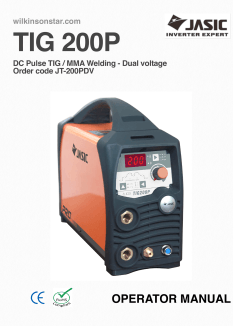
ZIKA OWNER`S MANUAL I-COMBO
ZIKA
OWNER`S MANUAL
I-COMBO
CONTENTS
1.
Contents........................................................................................................... 1
2.
Safety warning ................................................................................................ 2
3.
Machine description ....................................................................................... 3
4.
Technical parameters table ............................................................................ 4
5.
Installation instruction .................................................................................... 5
6.
Panel function instruction .............................................................................. 8
7.
Operation instruction...................................................................................... 9
8.
Notes or preventive measures ....................................................................... 10
9.
Questions to be run into during welding ...................................................... 11
10. Maintenance ..................................................................................................... 12
11. before checking ............................................................................................... 12
11. Troubleshooting and faults finding ................................................................ 13
·OWNER’S MANUAL·
-1-
I-COMBO
SAFETY WARNING!
On the process of welding or cutting, there will be any possibility of injury,
so please take protection into consideration during operation. For more
details please review the Operator Safety Guide, which complies with the
preventive requirements of the manufacturer
Electric shock——May lead to death !!
●
●
●
●
Set the earth fitting according to applying standard.
Forbidden to touch the electric parts and electrode when the skin is bare, wearing
wet gloves or clothes.
Make sure you are insulated from the ground and the workshop.
Make sure you are in safe position.
Fumes and gases——May be harmful to health!
●
●
Keep your head out of the gas and fume.
When arc welding, ventilators or air extractor should be used to avoid breathing gas.
Arc radiation——Harmful to your eyes and burn your skin.
Wear suitable helmet and light filter, wear protective garment to protect eyes and
body.
● Prepare suitable helmet or curtain to protect looker-on.
●
Fire
Welding spark may cause fire, make sure there is no tinder stuff around the welding
area.
●
Noise——Excessive noises will be harmful to hearing .
●
●
Use ear protector or others means to protect ear.
Warn looker-on that noise is harmful to hearing.
Malfunction——When trouble happens, contact with authorized professionals
●
●
If trouble happens during installation and operation, please follow this manual
instruction to check up.
If you fail to fully understand the manual, or fail to solve the problem with the
instruction, you should contact with the suppliers or the service center for
professional help.
WARNING!
Creepage-protecting switch should be added when using the machine!!!
·OWNER’S MANUAL·
-2-
I-COMBO
MACHINE DESCRIPTION
I-COMBO have arc welding, sticking and plasma cutting three processes, which adopt the
most advanced inverter technology.
The development of inverter gas-shielded welding equipment profits from the development
of the inverter power supply theory and components. Inverter gas-shielded welding power
source utilizes high-power component MOSFET to transfer 50/60HZ frequency up to
100KHZ, then reduce the voltage and commutate, and output high-power voltage via PWM
technology. Because of the great reduce of the main transformer’s weight and volume; the
efficiency increases by 30%. The appearance of inverter welding equipment is considered
to be a revolution for welding industry.
The welding power source can offer stronger, more concentrated and more stable arc.
When stick and work piece get short, its response will be quicker. It means that it is easier
to design into welding machine with different dynamic characteristics, and it even can be
adjusted for specialty to make arc softer or harder.
As sticking and arc welding ,outer characteristic of welding machine is constant
current .Welding current will not be changed with arc length and current is stable very
much .As plasma cutting ,after arc has pressed forcedly by air which is flowing
rapidly ,temperature is rise to 10000-15000℃ and it is up to high coinable situation then
strong plasma arc has been formed .Cutting metal rapidly with plasma arc, heat is
concentrated and energy is used effectively and smooth cutting section can be got.
I-COMBO can be used in welding and cutting of mild steel, stainless steel, alloy steel,
copper and other color metal .It has lightness, high efficiency, energy-saving, stabilizing
and reliable,
Welcome to purchase products of our company and make suggestions, we will try our best
to perfect our products and service.
CAUTION!
The machine is mainly used in industry. It will produce radio wave, so the
worker should make fully preparation for protection.
·OWNER’S MANUAL·
-3-
I-COMBO
TECHNICAL PARAMETERS TABLE
Model
I-COMBO
Item
Input voltage
(V,Hz)
AC220±15%, 50/60
Input power capacity
(KVA)
6
No-load loss(W)
40
Duty cycle(%)
60
Power factor
0.73
Efficiency(%)
80
Insulation class
F
Protection
IP21
Weight(Kg)
14
Dimension(mm)
432x204x302
Arc-welding
Sticking
Plasma
cutting
Input current
(A)
26.4
34
31
Rate output current
(A)
160
160
40
Currentadjustment range
(A)
10-160
10-160
20-40
No-load voltage
(V)
62
62
260
16
26
96
--
--
Ǿ1.2
Air compress (Mpa)
--
--
0.4
Gas flow(L/min)
2-5
--
80
Thickness(mm)
--
--
1-12
Touch
HFoscillate
Work voltage
(V)
Inter-diameter of burner
(mm)
Arc polite model
·OWNER’S MANUAL·
HFoscillate
-4-
I-COMBO
INSTALLATION INSTRUCTION
Air regulator installment and operation
1.
2.
3.
4.
5.
Tight and seal the copper air hole at IN and OUT terminal by high pressure rubber
tube firmly .
Tight and seal the meter.
Fix the connecting shelf with screw as the regulator position.
Get down the plastic screw and fix the regulator on the shelf.
Turn on the air valve, turn up the pressure adjusting knob, Turn the pressure to rated
volume(meter inside shows KG), and then put down the knob.
Regulator installment
6.
7.
Scale of the meter is as
follow.The volume in the picture
is 4 kg.
If the water in the gas filtering
bottle is too much, please turn on
the water valve to let the water
go out.
·OWNER’S MANUAL·
-5-
I-COMBO
INSTALLATION INSTRUCTION
The plasma cutter is equipment with power voltage compensation equipment. When the
power voltage fluctuates between±15% of rated voltage, it still can work normally.
When the machine is used with long cables, in order to prevent voltage form going down,
bigger section cable is suggested. If the cable is too long, it may affect the performance of
the power system. So we suggest you using cables of configured length.
1. Make sure the intake of the machine is not blocked or covered, otherwise the cooling
system could not work.
2. Use inducting cable whose section is not less than 6 mm² to connect the machine to the
ground.. The way is from the connecting screw in the back of the power source, or make
sure ground firmly. For absolute safety, both ways can be used.
3. When use MMA(ARC)function.
1) Make sure the cable, holder and fastening plug have been connected with the ground. Put
the fastening plug into the fastening socket at the “-“terminal and fasten it clockwise.
2) Put the fastening plug of the cable to fastening socket of “+” terminal at the front panel,
fasten it clockwise, and the earth clamp at the of the terminal clamps the work piece.
3) Please patty attention to the connecting terminal ,DC welding machine has two
connecting ways: positive connection and negative connection. Positive connection:
holder connects with “-”terminal, while work piece with the “+” terminal .Negative
connection: work piece with the “-”terminal. Choose suitable way according to working
situation. If unsuitable choice is made, it will cause unstable arc, more spatters and
conglutination, If such problems occurs, problems occur, please change the polarity. Of
the fastening plug.
4. When use TIG function.
1) Connect well the protecting gas source, Gas supply passage includes cylinder, argon
meter and gas pipe. The joint part of the pipe should be tighten by hoop or other things in
order to prevent leakage and air from coming in.
2) Install the air-electricity system plug to the socket in the panel and fix it clockwise .Air plug
of the cutting torch and arc-keeping cable should be connected to relevant socket, and fix
the screw.
3) Put the loop cable plug to the fastening socket,and tighten clockwise ,another terminal
holds the work piece.
·OWNER’S MANUAL·
-6-
I-COMBO
INSTALLATION INSTRUCTION
5. Cutting Function
1) Use pressure-resisting air pipe to connect the air intake and compressed air source,
and use hoop and other way to tighten the joint. Air source should supply suitable
pressure, flow and be dry. If your air source does not meet the above requirements,
you should consider using sole compressor of the right power and air-decompressing
filter, in order to supply suitable pressure and eliminate the impurity and moisture in
the air.
2) Install the air-electricity system plug to the socket in the panel and fix it clockwise. Air
plug of the cutting torch and arc-keeping cable should be connected to relevant socket,
and fix the screw.
3) Put the fastening plug of the cable to fastening socket of “+” terminal at the front panel,
fasten it clockwise, and the earth clamp at the other terminal clamps the work piece.
4) On the panel potentiometers scale sink-screen, the inner scale is the Cutting current
Adjustment Scope, the inner scale is the Cutting Current Adjustment Scope of of
I-COMBO is 20-40.
6. According to input voltage grade, connect power cable with, power supply box of
relevant voltage grade. Make sure no mistake and the voltage difference among
permission range. Connect the cable as the picture shows. You can start cutting.
·OWNER’S MANUAL·
-7-
I-COMBO
PANEL FUNCTION INSTRUCTION
I-COMBO
·OWNER’S MANUAL·
1
Delay time of shutting off gas
2
Output current adjustment
3
Abnormal indicator
4
Power indicator
5
Power switch
6
Negative output terminal
7
Gas-electricity system output terminal
8
Torch switch socket
9
Positve output terminal
10
TIG/MMA welding current adjustment scale
11
Cut current adjustment scale
-8-
I-COMBO
OPERATION INSTRUCTION
1 TIG welding function
1) Turn on the power switch at the back panel, digital current meter is normal, fan begins to
wheel.
2) Open the valve of argon cylinder, adjust the volume of flow meter and make it is
adequate to welding.
3) Press switch of torch, electromagnetic valve is started. Sound of HF arc striking can
be heard, at the same time argon is flowing from torch burner. NOTES: When
welding is first operated, user must press switch of torch several seconds and
begin to weld until all of air is be drained out. When welding is over, argon will still
flow out in several seconds in order to protect welding spot before cooled
down .So torch must be kept welding place sometime before arc has been
extinguished.
4)Set suitable welding current and make sure welding current is adequate to thickness
of work piece and process demand.
5)It is 1-4 mm from welding tungsten electrode to work piece, press control knob of
torch ,burn and strike arc , sound of HF arc-striking will be diminished .The welding
machine can be operated now.
2 MMA(ARC)function
1) Open power switch of front panel, fan begins to work.
2) Make sure function switch of front panel is on “down” position that is sticking.
Impulse changeover switch and knob of current down-slope time will not work.
3) Make sure welding current is adequate to thickness of work piece.
3 Cutting function
1)Open the power switch of front panel, make the power switch is in “on” position .At
this time indicator of power switch is on .Screen will show the current volume.
2)Adjust the gas pressure and make it is adequate to machine, open the valve of
Pressed air .
3)Press the control knob of torch, electromagnetic valve is starting ,sound of HF
Arc-striking can be heard and burner of torch should flow out gas (Burner of
arc-supporting cutter should spurt fire )
4)It is 1mm from copper tip to work piece (it is further if it is arc-supporting
Cutter), press knob of torch and burn and strike arc, sparks of HF arc-striking will
Diminished immediately .User can begin to cut.
5)Keep the trip of the cutting torch contact the material; put the button of the cutting
torch to make arc. And the high frequency will disappear after the electronic sound.
And then cutting machine can begin to cut. After the initiation, take note that the
nozzle should be kept about 1 mm away from the material, which do help to the
nozzle.
·OWNER’S MANUAL·
-9-
I-COMBO
NOTES OR PREVENTIVE MEASURES
1、Environment
1) The machine should be operated in dry environments with humidity levels of max 90%.
2) Ambient temperature should be between -10 to 40 degrees centigrade.
3) Avoid welding in sunshine or rain.
4) Do not use the machine where conductive dust or corrosive gas are present.
5) Avoid gas welding in the environment of strong airflow.
2、Safety norms
The welding machine is installed with protection circuit against over voltage and current
as well as overheating. When voltage and output current and temperature of machine
exceed the required standard, welding machine will stop working automatically.
However, overuse (such as over voltage) will still result in damage to the welding
machine. To avoid this, the user must pay attention to the following.
1) The working area is adequately ventilated!
The welding machine is powerful machine, when it is being operated, it generated by
high currents, and natural wind will not satisfy machine cool demands. So there is a fan
in inter-machine to cool down machine. Make sure the intake is not in block or covered,
it is 0.3 meter from welding machine to objects of environment. User should make sure
the working area is adequately ventilated. It is important for the performance and the
longevity of the machine.
2)Do not over load!
The operator should remember to watch the max duty current (Response to the
selected duty cycle). Keep welding current is not exceed max duty cycle current.
Over-load current will damage and burn up machine.
3)No over voltage!
Power voltage can be found in diagram of main technical data. Automatic
compensation circuit of voltage will assure that welding current keep in allowable
arrangement. If power voltage is exceeding allowance arrangement limited, it is
damaged to components of machine. The operator should understand the situation and
take preventive measures.
4)There is a grounding screw behind welding machine, there is grounding marker on it
Mantle must be grounded reliable with cable which section is over 6 square millimeter
In order to prevent from static electricity and leaking.
5)If welding time is exceeded duty cycle limited, welding machine will stop working
for protection. Because machine is overheated, temperature control switch is on “ON’’
position and the indicator light is red. In this situation, you don’t have to pull the plug, in
order to let the fan cool the machine. When the indicator light is off, and the
temperature goes down to the standard range, it can weld again.
·OWNER’S MANUAL·
- 10 -
I-COMBO
QUESTIONS TO BE RUN INTO DURING WELDING
Fittings, welding materials, environment factor, supply powers maybe have something to
do with welding. User must try to improve welding environment.
A.
Black welding spot
——Welding spot is not prevented from oxidizing .User may check as following ::
1. Make sure the valve of argon cylinder is opened and its pressure is enough. argon
cylinder must be filled up to enough pressure again if pressure of cylinder is be low
0.5Mpa .
2. Check if the flow meter is opened and has enough flow .User can choose different flow
according to welding current in order to save gas .But too small flow maybe cause
black welding spot because preventive gas is too short to cover welding spot .We
suggest that flow of argon must be kept min 5L/min.
3. Check if torch is in block.
4. If air is flowing powerfully in welding environment, that can lower welding quality.
B. Arc-striking is difficult and easy to pause :
1. Make sure quality of tungsten electrode is high .
2. Grind end of the tungsten electrode to taper .If tungsten electrode is not grinded, that
will be difficult to strike arc and cause unstable arc .
C、Output current not to rated value:
When power voltage departs from the rated value, it will make the output current not
matched with rated value; when voltage is lower than rated value, the max output may
lower than rated value.
D. Current is not stabilizing when machine is been operating:
It has something with factors as following:
1. Electric wire net voltage has been changed.
2. There is harmful interference from electric wire net or other equipment.
E. When use MMA welding ,too much spatter:
1. Maybe current is too big and stick’s diameter is too small;
2. Output terminal polarity connection is wrong, it should apply the opposite polarity at
the normal techniques, which means that the stick should be connected with the
negative polarity of power source, and work piece should be connected with the
positive polarity. So please change the polarity.
·OWNER’S MANUAL·
- 11 -
I-COMBO
MAINTENANCE
CAUTION:
Before Maintenance and checking, power must be turned off, and before
Opening the housing, make sure the power plug is pulled off..
1. Remove dust by dry and clean compressed air regularly, if welding machine is
operated in environment where is polluted with smokes and polluted air, the machine
need remove dust every month.
2. Pressure of compressed air must be inside the reasonable arrangement in order to
prevent damaging to small components of inter-machine.
3. Check inter circuit of welding machine regularly and make sure the cable
Circuit is connected correctly and connectors are connected tightly (especially insert
connector and components). If scale and loose are found, please give a good polish
to them, then connect them again tightly.
4.Avoid water and steam enter into inter-machine, if them enter into machine, please dry
inter-machine then check insulation of machine.
5. if welding machine will not be operated for long time, it must be put into packing box
and stored in dry environment.
BEFORE CHECKING
WARNING
Blind experiment and careless repair may lead to more problem of the
machine that will make formal check and repair more difficult. When the machine is
electrified, the naked parts contain life-threatening voltage. Any direct and indirect
touch will cause electric shock, and severe electric shock will lead to death.
Notice: In the period of guarantee maintenance, if user makes wrong check and
repair for our induction power without our permission, the free maintenance
guarantee offered by the supplier will be invalid.
·OWNER’S MANUAL·
- 12 -
I-COMBO
TROUBLESHOOTING AND FAULTS FINDING
Notes:The following operations must be performed by qualified electricians
with valid certifications that proves their ability and knowledge. Before
maintenance,contact with our for authorization is sugested.
I-COMBO
Faults
1. Power indicator is not lit,
fan is not working, and
there is no welding output.
2. Indicator of power switch
is lit, fan is not working or
revolves several circles
and stopped, there is no
welding output.
3. Fan is working, abnormal
indicator is not on, sound
of HF arc striking can be
heard, wipe arc welding
cannot strike arc.
4. Abnormal indicator is not
lit, sound of HF arc striking
can be heard, wiping arc
welding can strike arc.
5. Abnormal indicator is not
lit, sound of HF arc striking
can be heard, and there is
no welding and cutting
output.
·OWNER’S MANUAL·
Resolvable Methods
1. Power switch is damaged.
2. Make sure electrify wire net, which is connected to input cable
is working.
3. Make sure if input cable is broken circuit.
1. Maybe input cable is connected to 380v power cause over
voltage protection circuit is starting. Make input cable is
connected to 220V power, replace safety tube then open
machine again.
2. Transformer of assistant power is damaged.
3. Fuse is broken.
4. Short voltage protection is starting.
5. Cable, which is from switch to power panel, is loosed, tighten it
again.
6. 24Vrelay of main return circuit of power panel is not close or
damaged, check 24V power and relay .If relay is damage,
replace it with some model.
1. Measure voltage of positive and negative electrode is about
DC308v from power panel to VH-07 insert of MOS board by
AVO meter.
a) If it is broken circuit and insert cable of Silicon Bridge is
poor contact.
b) If one of four high electrolytic (about 470UF/450V) of
power panel is leaking, replace it.
2. Assistant power source supply power abnormally, normal
voltage is DC 24V.
3. Check if all kinds of connect and insert cable is poor contact.
4. Check if there is some question in control circuit, connect with
seller.
If control cable of torch is broken.
1. Cable of torch is broken.
2. Grounding cable is broken or is not connected to work piece.
3. Output terminal of positive electrode or there is loose between
electrify output terminal of torch and inter-machine.
1. Primary cable of arc-striking transformer is poor contact with
power panel, tighten it again.
2. Arc-striking tip is oxidized or distance is too far, give a good
polish oxide of burner or adjust it is 1 mm between burners.
3. Changeover switch of sticking/arc welding is damaged, replace
it.
4. Some of components of HF arc striking check and replace it.
- 13 -
I-COMBO
6. Abnormal indicator is on,
there is no output.
7. Welding output current is
not stable or out of control
of
potential,
current
sometimes is low and
sometimes is high.
8. Sticking spatter is much,
caustic electrode is welded
difficultly.
9. Ability of welding and
cutting is not enough, arc
is broken.
1. Maybe it is overheated protection, please close machine first,
and then open the machine again after abnormal indicator is
out of work.
2. Maybe it is overheated protection, wait for 2-3 minutes
(argon-arc welding does not has overheated protection
function.) and machine can be operated normal.
3. Maybe inverter circuit is fault, please pull up the supply power
plug of the main transformer which is on MOS board (VH-07
insert which is near the fan) then open the machine again.
a) If abnormal indicator is still lit, close machine and pull up
supply power plug of HF arc-striking power source (which
is near the VN-07 insert of ventilator), then open machine:
i.
If abnormal indicator is still on, some of fillister of
MOS board is damaged, find out and replace it with
same model.
ii.
If abnormal indicator is not lit, up-slope transformer of
HF arc-striking circuit is damaged, replace it.
b) If abnormal indicator is not lit ,
i.
Maybe transformer of middle board is damage,
measure inductance volume and Q volume of main
transformer by inductance bridge (L=0.9-1.6mH
Q>35) .If volume of inductance and Q are too low,
please replace it.
ii.
Maybe second rectifier tube of transformer is
damaged, find out and replace rectifier tube of same
model.
4. Maybe feedback circuit is opened.
1. 1K potential is damaged, replace it.
2. All kinds of connectors are poor contact, check them.
1. Electrode is a connected wrong, exchange electrode of
grounding cable and holder cable.
1.
2.
3.
4.
5.
6.
7.
Voltage of input cable is low.
Grounding cable is poor contact or too long.
Pressure of air is too high or too low.
Electrode of burner is coordinated weakly.
Filter capacity of machine (470Ų/450v) is lose efficacy.
Electrode is damp or bad.
Rate current is too low.
If machine cannot work normal after it has been adjusted and checked and maintained
according to above demands, please contact with seller or department of after-sale service
of our company.
·OWNER’S MANUAL·
- 14 -
I-COMBO
© Copyright 2025


