Data sheet TE 60.55
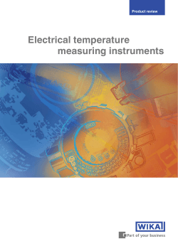
Electrical temperature measurement Resistance thermometer Model TR55, with spring-loaded tip WIKA data sheet TE 60.55 for further approvals see page 6 Applications Bearing temperature measurement on: ■■ Pumps ■■ Gears ■■ Motors Special features ■■ Application ranges from -50 ... +500 °C ■■ Compact design ■■ Spring-loaded tip ■■ Explosion-protected versions Ex i, Ex n Resistance thermometer with spring-loaded tip, model TR55 Description The model TR55 resistance thermometer is ideally suited for the measurement of surface temperature at bearing shells on pumps, gears or motors under dry ambient conditions at the measuring tip. The spring-loaded, flat measuring tip ensures a constant contact pressure of the thermometer on the outer surface of the bearing shell. The optimum insertion depth can be set by means of a compression fitting. Analogue or digital transmitters built into the connection head are capable of making various output signals available, for example 4 ... 20 mA, HART® protocol, PROFIBUS® PA or FOUNDATION™ Fieldbus. WIKA data sheet TE 60.55 ∙ 12/2014 Page 1 of 6 Sensor Compression fitting Sensor connection method The compression fitting enables simple, on-site adjustment to the required insertion length. ■■ 2-wire ■■ 3-wire ■■ 4-wire Due to the length of the compression fitting itself, the minimum neck length N is 40 mm for parallel threads and 55 mm for NPT threads. Sensor tolerance value per DIN EN 60751 ■■ Class B ■■ Class A ■■ Class AA ■■ Ferrule material: stainless steel Ferrules from stainless steel are only adjustable once; once the fitting has been loosened, sliding along the thermowell is no longer possible. The combinations of a 2-wire connection with class A or class AA are not permissible, since the lead resistance of the measuring insert negates the higher sensor accuracy. Ferrules from PTFE are not recommended. For detailed specifications for Pt100 sensors, see Technical information IN 00.17 at www.wika.com. Without process connection Process connections This version is designed mainly for mounting in one of the available compression fittings. All process connections are manufactured from stainless steel. Other materials are available on request. The neck length N specifies the height of the hexagon below the head. ■■ Head JS: 7 mm ■■ Head B: 10 mm The insertion length A (U1 bzw. U2) can be customised. The neck length N depends on the type of the process connection selected. 11010371.01 Components model TR55 Legend: Connection head Process connection (compression fitting) Support tube Terminal block Measuring insert / measuring tip (spring-loaded, spring travel approx. 3 - 4 mm) Possible combinations of electrical connection, diameter support tube/measuring tip, number of sensors and sensor connection method Electrical connection Connection head JS Connection heads form B Connection heads form B Page 2 of 6 Support tube / measuring tip Ø in mm 6, 3 6, 3 8, 6 Sensor 1 x Pt100 Sensor connection method 2-wire 3-wire 4-wire x x x x x x x x x Sensor 2 x Pt100 Sensor connection method 2-wire 3-wire 4-wire x x x x x x WIKA data sheet TE 60.55 ∙ 12/2014 Support tube Serves for the fastening of the compression fitting only and is open at the measuring tip (not water-, dust- or gas-tight). ■■ Material: stainless steel Support tube Ø in mm Process connection 6 or 8 G¼B G⅜B G½B ¼ NPT ½ NPT Maximum possible insertion length A 1) in mm with sensor length FL 65 75 80 85 105 125 230 35 35 35 20 20 45 45 45 30 30 50 50 50 35 35 55 55 55 40 40 75 75 75 60 60 95 95 95 80 80 200 200 200 185 185 250 220 220 220 205 205 1) Spring not loaded, spring travel approx. 3 to 4 mm (tolerance of insertion lengths ±2 mm) Permissible temperature ranges ■■ Application range: ■■ At the head: ■■ At the transmitter: ■■ Storage: -50 ... +500 °C -40 ... +80 °C (without transmitter) -40 ... +80 °C -40 ... +60 °C Connection head JS BS BSZ-H BSZ-HK BSZ BSZ-K BSS BSS-H BVS Model Material Cable outlet Ingress protection Cap Surface JS BS BSZ BSZ-K BSZ-H BSZ-HK BSS BSS-H BVS Aluminium Aluminium Aluminium Plastic Aluminium Plastic Aluminium Aluminium Stainless steel M16 x 1.5 M20 x 1.5 2) M20 x 1.5 2) M20 x 1.5 2) M20 x 1.5 2) M20 x 1.5 2) M20 x 1.5 2) M20 x 1.5 2) M20 x 1.5 2) IP 54 IP 65 4) IP 65 4) IP 65 4) IP 65 4) IP 65 4) IP 65 4) IP 65 4) IP 65 4) Cap with 2 screws Cap with 2 screws Hinged cover with cylinder head screw Hinged cover with cylinder head screw Hinged cover with cylinder head screw Hinged cover with cylinder head screw Hinged cover with clamping lever Hinged cover with clamping lever Screw cap Blue, lacquered 3) Blue, lacquered 3) Blue, lacquered 3) Black Blue, lacquered 3) Black Blue, lacquered 3) Blue, lacquered 3) Precision casting, electropolished 4) 2) Standard 3) RAL 5022 4) The indicated ingress protection does not apply for the open sensor tip. It is valid for the connection head of a correctly installed thermometer. WIKA data sheet TE 60.55 ∙ 12/2014 Page 3 of 6 Transmitter (option) Depending on the connection head used, a transmitter can be mounted within the thermometer. ○ Mounted instead of terminal block ● Mounted within the cap of the connection head – Mounting not possible Model T19 T24 T91.10 T91.20 T12 T32 T53 Description Connection head Transmitter model JS BS BSZ / BSZ-K BSZ-H / BSZ-HK BSS BSS-H BVS - Analogue transmitter, configurable Analogue transmitter, PC configurable Analogue transmitter, fixed measuring range Analogue transmitter, fixed measuring range Digital transmitter, PC configurable Digital transmitter, HART® protocol Digital transmitter FOUNDATION Fieldbus and PROFIBUS® PA T12 T19 T24 ○ ○ ○ ○ ○ ○ ○ ○ ○ ○ ○ ● ● ● ● T32 - ○ ○ ○ ○ ○ ● ● ● ● ● ● ● ● ○ ○ Explosion protection Without Optional Without Without Optional Optional Standard T53 T91.10 T91.20 ○ ○ ○ ○ ○ - Data sheet TE 19.03 TE 24.01 TE 91.01 TE 91.01 TE 12.03 TE 32.04 TE 53.01 Dimensions in mm Connection head model BSZ 11010380.05 Connection head model JS Legend: A (U1) Insertion length E Thread Ød Support tube Ø N Neck length FL Sensor length The combinations of process connection and connection head shown above are examples. Page 4 of 6 WIKA data sheet TE 60.55 ∙ 12/2014 Electrical connection 1 x Pt100, 2-wire 1 x Pt100, 4-wire 1 x Pt100, 3-wire 2 x Pt100, 2-wire yellow black white red white red white white red red red red red red red red white white white white white black yellow white 1 x Pt100, 4-wire 1 x Pt100, 3-wire red white 3160629.06 Connection head form B 1 x Pt100, 2-wire red white red red white red red red red red red white white white white 2 x Pt100, 2-wire 2 x Pt100, 4-wire 2 x Pt100, 3-wire red red white yellow black 3383942.03 Connection head JS white red white yellow black yellow black red red red red red white white black black black white white black black yellow yellow yellow yellow For the electrical connections of built-in temperature transmitters see the corresponding data sheets or operating instructions. WIKA data sheet TE 60.55 ∙ 12/2014 Page 5 of 6 Explosion protection (option) Approvals (option) Resistance thermometers of the TR55 series are available with an EC-type examination certificate for “intrinsically safe”, Ex i, ignition protection. These instruments comply with the requirements of 94/9/EC (ATEX) directive for gases and dusts. ■■ IECEx, international certification for the Ex area The classification/suitability of the instrument (permissible power Pmax as well as the permissible ambient temperature) for the respective category can be seen on the EC-type examination certificate and in the operating instructions. Built-in transmitters have their own EC-type examination certificate. The permissible ambient temperature ranges of the built-in transmitters can be taken from the corresponding transmitter approval. The system operator is responsible for using suitable thermowells. ■■ NEPSI, ignition protection type “i” - intrinsic safety, ignition ■■ ■■ ■■ ■■ ■■ protection type “iD” - dust protection through intrinsic safety, China EAC, import certificate, ignition protection type “i” intrinsic safety, ignition protection type “iD” - dust protection through intrinsic safety, customs union Russia/ Belarus/Kazakhstan GOST, metrology/measurement technology, Russia INMETRO, Institute of Metrology, ignition protection type “i” - intrinsic safety, ignition protection type “iD” - dust protection through intrinsic safety, Brazil KOSHA, ignition protection type “i” - intrinsic safety, ignition protection type “iD” - dust protection through intrinsic safety, South Korea PESO (CCOE), ignition protection type “i” - intrinsic safety, ignition protection type “iD” - dust protection through intrinsic safety, India CE conformity EMC directive 2004/108/EC, EN 61326 emission (group 1, class B) and interference immunity (industrial application) ATEX directive (option) 94/9/EC, EN 60079-0, EN 60079-11 Certificates (option) Certification type Measuring accuracy x 2.2 test report x 3.1 inspection certificate DKD/DAkkS calibration certificate x Material certificate x - The different certifications can be combined with each other. Approvals and certificates, see website Ordering information Model / Sensor / Explosion protection / Connection head / Terminal block, transmitter / Output signal / Process connection / Version and material of the threaded connection / Support tube diameter / Thread size / Measuring element / Connection method / Temperature range / Insertion length A / Neck length N (MH) / Certificates / Options Page 6 of 6 WIKA data sheet TE 60.55 ∙ 12/2014 WIKA Alexander Wiegand SE & Co. KG Alexander-Wiegand-Straße 30 63911 Klingenberg/Germany Tel. +49 9372 132-0 Fax +49 9372 132-406 info@wika.de www.wika.de 12/2014 EN © 2009 WIKA Alexander Wiegand SE & Co. KG, all rights reserved. The specifications given in this document represent the state of engineering at the time of publishing. We reserve the right to make modifications to the specifications and materials.
© Copyright 2024


