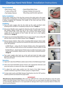
installation instructions
installation instructions
Easi-Plan Bidet Frame 820mm ref: EPBI-05-1005
Easi-Plan Bidet Frame 980mm ref: EPBI-05-1505
Easi-Plan Bidet Frame 1180mm ref: EPBI-05-2005
®
EASI-PLAN®
installation instructions
Parts supplied
A
B
1 x Bidet Frame
(incorporating 1 x 1 1/4”
Waste Elbow with Rubber
Insert, 2 x Oval Sound Deadening Pad, 2 x Brass Elbow
1/2” Female – 1/2” Female,
2 x Elbow Debris Stopper)
E
2 x Rubber Sound
Deadening Pad
for Feet
F
6 x M6
Washer
I
D
6 x M6 x 65mm
Coach Bolt
G
2 x M10 x
180mm Bolt
J
2 x M8
Washer
1
C
H
2 x M10 x
110mm Bolt
K
2 x Unistrut
Fixing
6 x White Wall
Plug 10mm
2 x M8 x
30mm Bolt
L
2 x Wall
Fixing Foot
2 x Bolt
Location Block
M
N
2 x Bolt Retaining
Clip
6 x M10 Push Fit
Fastening Nuts
Q
R
2 x Chrome
Isolation Valve
2 x Clear Bidet
Fixing Bolt
Shroud
O
P
2 x Bidet Fixing Bolt
2 x Bidet Fixing Nut
S
T
2 x Bidet
Installation
Bung
U
2 x Washer
2 x Chrome
Cover Cap
Tools required (not supplied)
• Tape Measure
• Level
• Pencil
• Electric Drill
• 10mm Drill Bit
• Screwdriver PH3
• Large Straight Blade Screwdriver
• Spanner / Socket Set
• Hacksaw
• PTFE Tape
2
Important Information
PLEASE READ THESE INSTRUCTIONS THOROUGHLY BEFORE STARTING INSTALLATION.
Check the pack and make sure you have all the parts listed.
Remove all cardboard protection attached to the frame prior to installation.
All floor types need to be as flat and level as possible.
When drilling or fixing into walls or floor it is essential that you check for pipes or wires before
commencing.
Site Preparation
All floor types need to be clean, dry and dust free.
All floor types need to be as flat and level as possible.
Floor boards must be securely fixed down prior to installation.
Adjusting the frame
The frame feet can be adjusted to allow for uneven floors and finished floor build up. The frame allows for an additional 280mm adjustment on the standard height. Using a spanner or socket, loosen the
bolts just above the feet and extend the feet to your desired height. Ensure that the frame is square
using a level before tightening the bolts using a socket or spanner.
The internal frame (incorporating the bidet fixing points and brass elbows) will need to be set to
the desired height. Loosen the bolts on either side of internal frame and raise or lower the unit
appropriately. Ensure that the internal frame is square using a level before tightening the bolts using a
socket or spanner.
Before You Start
The first phase of installation is the securing of the frame to wall and floor. There are two methods of
installation; either individual fixing or unistrut (rail) mounted fixing. The unistrut (rail) mounted system is
normally used where multiple frames are to be mounted next to each other, i.e., a basin frame next
to a WC frame or a row of frames. This is also the best option when fixing to stud walls rather than solid
walls. Bypass Step 2 if you plan to individually fix the frame.
Note: The rail kit is an optional extra and can be purchased from the Sales Office on 0845 8 50 50 40.
3
Step 1
Important! Set the frame to the bidet
manufacturer’s recommendations for the
fixing bolts, Hot & Cold feed and Waste Elbow
location / spacing. The Bidet Bolts (H) can be
set at either 180mm or 230mm centres
Step 2
First ensure that the rail is the correct length for
the frames to be mounted. If necessary, cut the
rail to the required length (standard sizes available
are 1.08m, 1.8m & 3.0m) using a hacksaw. Mark
a horizontal line 80mm lower than the top of your
frame using a pencil i.e., if the frame measures at
820mm high, you should mark your horizontal line
at 740mm.
Using the pencil line as the centre point for the rail,
secure it to the wall using the fixings supplied and
ensure that it is mounted evenly using a level.
Note: For individual installation please omit this step.
Step 3
Fix the Rubber Sound Deadening Pads (B) to the
Basin Frame (A) feet. These help reduce noise
transmission.
Step 4
Space the frame off the back wall to the
required distance. The minimum installation
depth is determined generally by the width of
the frame leg plus the services running behind
the frame. A tolerance of 120 - 265mm from wall
to front face of the frame can be achieved with
standard ‘in the box’ parts.
Note: An extension set is available which offers
a further 160mm and can be purchased from
the Sales Office on 0845 8 50 50 40.
4
Mark through
using a pencil
Solid floor
application
Step 5
Using a pencil, mark through the four holes in
the Basin Frame (A) feet the fixing hole positions.
Timber floor application
Secure the feet into position by fixing the
four M6 x 65mm Coach Bolts (C) and four M6
Washers (E) using a PH3 Screwdriver or Spanner
and the pencil marks as a guide.
In the event of the Coach Bolts (C) being
unsuitable for your particular application,
please replace these items with your choice of
comparable fixing.
Solid floor application
Drill four holes in the floor using a drill and 10mm
drill bit using the pencil marks as a guide. Insert
the four 10mm White Wall Plugs (D) into the
holes. Secure the feet into position by fixing the
four M6 x 65mm Coach Bolts (C) and four M6
Washers (E) using a PH3 Screwdriver or Spanner
and the Wall Plug locations as a guide.
5
Timber floor
aplication
Fig. 1
Step 6
Place the two Bolt Location Blocks (L) into either
side of the top frame profile. Dependant on
the depth required and measured in Step 3,
take either the two M10 x 180mm Bolts (F) for
a tolerance of 120 - 200mm, or the two M10 x
110mm Bolts (G) for a tolerance of 190 - 265mm.
Thread the two bolts (F) or (G) through the Bolt
Location Blocks (L).
Fasten the two Wall Fixing Feet (K) to the bolts
(F) or (G) to the desired depth measured in
Step 3. The wall fixing feet can be fixed to
the wall in a number of ways. Generally they
should be installed with the screw hole pointing
downwards for unistrut (rail), however where
achievable they can be installed with the screw
holes pointing outwards for ease of fixing.
Insert the two Bolt Retaining Clips (M) into either
side of the top frame profile with the raised
face to the front. This captivates the bolts whilst
still allows for tightening with a straight bladed
screwdriver as needed. Fit two M10 Push Fit
Fastening Nuts (M) per bolt; the first at either end
of the thread to lock the bolt into position.
Note: To achieve a minimum depth of 120mm
you should only affix one M10 Push Fit Fastening
Nut (M) per bolt and not two as instructed
above.
6
Step 8
Connect the two Bidet Fixing Bolts (O) to the
Bidet Frame (A).
Step 7
Using a pencil, mark through the two holes in
the Wall Fixing Feet (K) the fixing hole positions.
Solid wall fixing
Drill two holes in the wall using a drill and 10mm
drill bit using the pencil marks as a guide. Insert
the two 10mm White Wall Plugs (D) into the
holes. Secure the feet into position by fixing the
two M6 x 65mm Coach Bolts (C) and two M6
Washers (E) using a PH3 Screwdriver and the
Wall Plug locations as a guide.
Unistrut (Rail) Fixing
Insert the two unistrut fixings (J) into the unistrut
(rail), then attach the Wall Fixing Feet (K) to the
unistrut using one M8 x 30mm Bolt (H) and one
M8 Washer (I) per Wall Fixing Foot (K).
7
Step 9
Connect the Hot & Cold Water Supply to the
two Brass Elbows 1/2” Female – 1/2” Female and
connect the Basin Waste pipework to the 1 1/4”
Waste Elbow with Rubber Insert. Ensure that all
connections are tested for leaks.
Install any other pre-wall frames as required and
install either timber or metal studwork either
side of the frame/ before then plaster boarding
and tiling.
Note: The frame comes with holes in either
leg; these can be used to fix a screw into the
studwork at either side for added strength as
required.
* The frame is now ready for 2nd Fix Installation *
Step 10
Remove the debris stoppers from the two Brass
Elbows 1/2” Female – 1/2” Female and fit the
two Chrome Isolation Valves (S) using a layer of
PTFE tape.
8
Step 11
If the two Bidet Fixing Bolts (O) need any further
adjustment at this stage they can be wound
down to the desired length using a straight
bladed screwdriver. Place the two Clear Bidet
Fixing Bolt Shrouds (R) over the two Pan Fixing
Bolts (O) and cut to suit the length of the bolts
but also to allow for the two Bidet Fixing Nuts (P).
Offer the bidet (not supplied) into position then
secure to the wall using the two Bidet Fixing
Bolts (O), two Bidet Installation Bungs (S), two
Washers (T) and two Bidet Fixing Nuts (P). Place
the two Chrome Cover Caps (U) over the two
Bidet Installation Bungs (S).
Step 12
Fix the mono bidet mixer & waste (not supplied)
to the bidet (not supplied), then connect the
10mm tap tails to the Chrome Isolation Valves
(S). In the event that the tails are 3/8” Female,
discard the nut & olive from either Chrome
Isolation Valve (S) and fit the tap tails using a
layer of PTFE tape.
If you require any assistance or advice,
please contact the Helpline on 0845 8 50 50 40
9
Step 13
Fix the bottle trap (not supplied) to the bidet
waste (not supplied) and secure the waste into
the 1 1/4” Waste Elbow with Rubber Insert using
silicone grease.
10
Abacus House,
Jubilee Court, Copgrove,
Harrogate, HG3 3TB, England
t: 0845 8 50 50 40 f: 0845 8 50 50 30
e-mail: info@abacusdirect.co.uk
www.abacusdirect.co.uk
© Copyright 2009 Abacus Direct Limited - Version 1.01 27/07/09
Due to our commitment to continuous product development we
reserve the right to alter specifications without notice. Products are
guaranteed against manufacturing defects for the first purchaser
only and the guarantee is non-transferable. Our liability under any
guarantee expressed or implied is strictly limited to replacement of
defective goods or a refund at our discretion and no consequential
losses will be entertained. Proof of purchase will be required.
© Copyright 2025

