
NL-42 / NL-52 SERIAL INTERFACE MANUAL Sound Level Meter
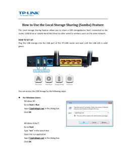
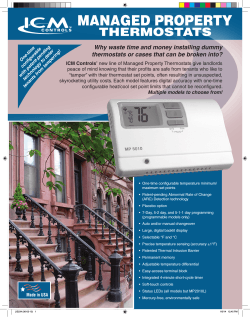
SERIAL INTERFACE MANUAL
Sound Level Meter
NL-42 / NL-52
3-20-41 Higashimotomachi, Kokubunji, Tokyo 185-8533, Japan
http://www.rion.co.jp/english/
Organization of the NL-42/NL-52 documentation
Documentation for the Sound Level Meter NL-42/NL-52 comes in three
parts, as listed below.
Instruction Manual
Describes operating procedures for the NL-42/NL-52, connection and use
of peripheral equipment such as a level recorder and printer, and use of the
SD memory card.
Serial Interface Manual (this document)
Describes communication with a computer, using the serial interface built
into the NL-42/NL-52. The manual covers the communication protocol,
use of control commands for the sound level meter, format of data output
by the sound level meter, and other topics.
Technical Notes
This document provides in-depth information about sound level meter
performance, microphone construction and characteristics, influence of
extension cables and windscreen on the measurement, and other topics.
* Company names and product names mentioned in this manual are usually
trademarks or registered trademarks of their respective owners.
i
ii
Organization of This Manual
This manual describes how to use the serial interface built into the NL-42/
NL-52. Besides the RS-232C serial interface standard, the unit also supports
USB. However, correct operation in combination with other USB devices is
not assured. If possible, you should avoid connecting other USB devices at
the same time.
The manual is divided into four chapters.
Chapter 1 covers points that are common to the RS-232C and USB interface.
Chapter 2 contains information for users of the RS-232C interface. USB users
need not read this chapter.
Chapter 3 contains information for users of the USB interface. RS-232C users
need not read this chapter.
Chapter 4 explains the interface commands. This chapter is for users of either
interface. You should read the explanation for the commands that operate the
functions you want to use.
Chapter 1
General Information
This chapter contains information that applies both to the RS-232C and USB
interface.
Chapter 2
RS-232C
This chapter explains connection to a computer and transfer principles using
the RS-232C interface.
Chapter 3
USB
This chapter explains connection to a computer, installing the USB driver
and how to use the USB interface.
Chapter 4
Commands
This chapter explains the commands used to control the NL-42/NL-52.
Information is given about command format, functions, and other relevant
points.
iii
Contents
Organization of the NL-42/NL-52 documentation .......................... i
Organization of This Manual ........................................................ iii
Chapter 1 General Information ......................................................1
Outline ............................................................................................2
Communication Cutoff ....................................................................3
Sleep mode ...............................................................................3
ECO setting ...............................................................................3
Power off ..................................................................................3
Auto shutdown ...........................................................................3
Rated Values ...................................................................................4
Chapter 2 RS-232C ..........................................................................5
Connection to a Computer ..............................................................6
Transfer Protocol ............................................................................8
Chapter 3 USB .................................................................................9
USB ............................................................................................. 10
Operating Environment ................................................................ 11
Installing the USB Driver .............................................................12
Installation procedure .............................................................12
Checking the virtual COM port .............................................. 17
Connection to a Computer ............................................................19
Disconnection from the Computer.................................................20
iv
Chapter 4 Commands ....................................................................21
Command......................................................................................22
Command types .......................................................................22
Command format .....................................................................22
Echo back ................................................................................24
Result code ..............................................................................24
Transfer codes..........................................................................24
Command list ..........................................................................25
Command Description .............................................................29
Command example ..................................................................62
v
vi
Chapter 1 General Information
Contents
Outline ............................................................................................2
Communication Cutoff ...................................................................3
Sleep mode ...............................................................................3
ECO setting ...............................................................................3
Power off ..................................................................................3
Auto shutdown...........................................................................3
Rated Values ...................................................................................4
1
Outline
The NL-42/NL-52 incorporate a serial interface. This interface allows the use of a
computer to make measurement parameter settings and to control the measurement.
It is also possible to send measurement results (current results as well as data stored
in the memory of the sound level meter) to the computer for further processing.
Standard terminal software (Hyper Terminal, etc.) can also be used as communication client.
2
Communication Cutoff
Sleep mode
When sleep mode is enabled, the unit enters the sleep state after the current
block has been sent. In the sleep state, the sound level meter does not send
or accept commands.
ECO setting
When ECO setting is selected, it will be enabled after a transmission of
current command is completed. After that, the sound level meter does not
send or accept commands (ECO setting disables the communication control
function).
Power off
During power off processing, communication is terminated after the current
command was sent.
Auto shutdown
Same as power off.
3
Rated Values
Guaranteed values
Case
Rated Values
Sound level meter reMax. 3 s
sponse time
Remarks
Result code 0004 (state error) response if
due to processing reasons
Send character interMax. 100 ms
val
−
Interval until sound
level meter enters
Max. 200 ms
idling state after sending data
After receiving data from the sound level
meter, wait at least 200 ms before sending
the next command
(For DOD?, at least 1 s)
Rated values
Case
4
Rated Values
Remarks
Block generation wait
time after receiving No limit
<STX>
−
Receive character inNo limit
terval timeout
−
Chapter 2
RS-232C
Contents
Connection to a Computer .............................................................6
Transfer Protocol ............................................................................8
5
Connection to a Computer
Connect the I/O connector on the bottom of the NL-42/NL-52 with a RS-232C
connector of a computer, using the optional RS-232C serial I/O cable CC-42R
as shown below. The performance of other cables will not be guaranteed.
Note that the performance of multiple units connection with RS-232C will
not be guaranteed.
Important
Do not connect the cable connector to the I/O
connector reversely.
I/O connector
Projection
With the notch up,
align it with the projection
of the I/O connector.
Open
the bottom cover
To computer
RS-232C serial I/O cable CC-42R
Setting of the sound level meter when using the RS-232C
When using RS-232C, set the communication interface for the sound level
meter following the steps below.
1. Press the MENU/ENTER key to bring up the menu list screen.
2. Use the
keys to select [I/O] and press the MENU/ENTER key. The I/O screen appears.
3. Use the
keys to select [Communication Interface] and press the
MENU/ENTER key. The communication control function screen
appears.
6
Connection to a Computer
4. Use the
key.
keys to select [RS-232C] and press the MENU/ENTER
5. Select the [Baud rate] on the I/O screen and press the MENU/ENTER
key. The baud rate screen appears.
keys to select baud rate (9600bps, 19200bps, 38400bps,
6. Use the
57600bps, 115200bps) and press the MENU/ENTER key.
7. Press the START/STOP key to return to the measurement screen.
The CC-42R serial I/O cable uses a 9-pin connector (female).
The cable is optional.
Shield
NL-42/NL-52
I/O connector
Computer
Note
When NL-42/NL-52 is connected to a computer, the
minimum measurement level of NL-42/NL-52 may
rise by the noise from a computer.
7
Transfer Protocol
Transfer principle:
Sync principle:
Baud rate:
Data word length:
Stop bits:
Parity check:
Flow control:
8
full duplex
asynchronous
9600 / 19200 / 38400 / 57600 / 115200 bps
8 bit
1 bit
none
X parameter
Chapter 3 USB
Contents
USB .............................................................................................. 10
Operating Environment ................................................................. 11
Installing the USB Driver .............................................................12
Installation procedure .............................................................12
Checking the virtual COM port .............................................. 17
Connection to a Computer ............................................................19
Disconnection from the Computer ................................................20
9
USB
The NL-42/NL-52 can use a USB connection for operation control and
transfer of data. To use the USB interface, a USB driver must be installed
on the computer.
Please download USB driver from our web site (http://www.rion.co.jp/english/).
Installation and operation procedures are explained in this manual.
Note that the performance of multiple units connection with USB will not
be guaranteed.
10
Operating Environment
Supported Operating Systems
- Microsoft Windows XP Professional (32 bit)
- Microsoft Windows 7 Professional (32 bit/64 bit)
- Microsoft Windows 8 Pro (32 bit/64 bit)
11
Installing the USB Driver
By connecting the NL-42/NL-52 to a computer with a USB cable, the NL42/NL-52 can be controlled remotely from the computer, and measurement
data can be sent to the computer in real time. To enable use of these functions,
you must first download driver software from the RION Corporation web site
and install this driver on the computer to be used with the NL-42/NL-52.
The driver will create a virtual COM port on the computer.
Installation procedure
When connecting the NL-42/NL-52 and the computer for the first time, install
the USB driver as follows.
1. Download the latest USB driver from the RION Co., LTD. web site
(http://www.rion.co.jp/english/).
When using 32 bit OS, execute the file “setup.exe” located in the
“installer_x86” folder.
When using 64 bit OS, execute the file “setup.exe” located in the
“installer_x64” folder.
The installation starts.
12
Installing the USB Driver
Follow the wizard to complete the installation.
Screens during installation are as follows.
13
Installing the USB Driver
Depending on your environment, [Windows Security] may be displayed. Click on “Install” or “Continue”.
2. Turn power to the NL-42/NL-52 on, select [I/O] and set [Communication Interface] to “USB”.
Important
The above steps must be completed before
connecting the USB cable.
3. Connect the NL-42/NL-52 to the computer with a USB cable.
Important
Connect the NL-42/NL-52 directly with the USB
cable to the computer. If the NL-42/NL-52 is
connected via a USB hub, normal operation is
not assured.
14
Installing the USB Driver
In case of Windows 7 and Windows 8
When the computer detects the NL-42/NL-52, the device driver software installation is started automatically. When the installation has been completed,
USB communication is enabled.
In case of Windows XP
When the computer detects the NL-42/NL-52, [Found New Hardware Wizard]
is started up. Proceed following the wizard.
Select “No, not this time”, and click on “Next>”.
Select “Install the software automatically (Recommended)”, and click on
“Next>”.
15
Installing the USB Driver
Click on “Continue Anyway”.
Click on “Finish”.
The driver installation creates a virtual COM port in the computer. For information on how to verify that the installation was successful, see the section
“Checking the virtual COM port” on next page.
16
Installing the USB Driver
Checking the virtual COM port
1. After installing the driver, set [Communication Interface] to “USB”
at the NL-42/NL-52 and connect the USB cable.
2. Open the Device Manager (“Hardware” tab under “Properties” in
My Computer).
17
Installing the USB Driver
3. Click on the + at the left of “Ports (COM & LPT)”.
The indication “RION USB to RS232C Converter Virtual COM Port” should
be shown as COM port name. If this is not shown, check the connection
between the NL-42/NL-52 and the computer (step 1). If there is an “×” over
the icon, the port is not functioning normally. Install the driver again.
18
Connection to a Computer
Connect the USB connector on the bottom of the NL-42/NL-52 with a USB
connector of a computer, using the optional (generic) A - mini B USB cable
as shown below.
Important
Be sure to connect the cable only after selecting
the [USB] setting.
USB connector (mini B)
Open
the bottom cover
To computer
A - mini B USB cable
Setting of the sound level meter when using the USB
When using USB, set the communication interface for the NL-42/NL-52
following the steps below.
1. Press the MENU/ENTER key to bring up the menu list screen.
2. Use the
keys to select [I/O] and press the MENU/ENTER key. The I/O screen appears.
3. Use the
keys to select [Communication Interface] and press the
MENU/ENTER key. The communication control function screen
appears.
4. Use the
key.
keys to select [USB] and press the MENU/ENTER
5. Press the START/STOP key to return to the measurement screen.
19
Disconnection from the Computer
NL-42/NL-52 will be recognized as “removable media”. Consequently, the
correct procedure as described below must be followed when disconnecting
the NL-42/NL-52.
1. Click on the “Safely remove hardware” icon in the right section of
the taskbar, and select “Safely remove USB Mass Storage Device
- Drive (*1)”.
*1: The drive letter (E in the example shown) will differ, depending on
the computer configuration.
2. When the message shown below appears, disconnect the USB
cable.
The NL-42/NL-52 is now properly disconnected.
20
Chapter 4 Commands
Contents
Commands ....................................................................................22
Command types.......................................................................22
Command format ....................................................................22
Echo back ................................................................................24
Result code ..............................................................................24
Transfer codes .........................................................................24
Command list ..........................................................................25
Command description .............................................................29
Command example ..................................................................62
21
Command
Command types
There are two types of commands: setting commands and request commands.
Setting command
This type of command serves for changing the sound level meter status or
measurement parameters. Only some commands of this type will produce a
response from the sound level meter. The response consists of status information returned after the setting command has been processed.
Request command
This type of command serves for getting information about unit settings and
for obtaining measurement data including display data and stored data. The
sound level meter returns the requested data.
Command format
Setting command
Command = “$” + “command name” + “,” + “parameter” + [CR] + [LF]
The basic components of a setting command are the command name and the
parameter. “$” at the beginning represents the processing state of the command and is automatically displayed. During the processing of the command,
“$” is not displayed and does not accept the command input. A comma is
used as delimiter between the command name and parameter, and the setting
command is terminated by a [CR]+[LF] (carriage return + line feed). The
setting command uses the CSV format.
Prohibited items
•
•
•
•
22
Spaces in a command name may not be omitted.
Spaces in a command name may not be doubled.
The “,” (comma) after the command name may not be omitted.
Japanese full-width characters are not allowed.
Command
Permitted items
•
•
Lower case may be used instead of upper case.
Upper case may be used instead of lower case.
Setting command examples
LCD Auto Off,Short[CR][LF]
lcd auto off, short [CR][LF]
LCDAuto
Off, Short[CR][LF]
LCD Auto Off Short[CR][LF]
Valid
Space after “,” may be omitted.
Valid
Command name in all lower
case is permitted.
Invalid
Spaces in command name may
not be omitted.
Invalid
Comma after command name
may not be omitted.
“ ” stands for a space.
Request command
Command = “command name” + “?” + [CR] + [LF]
The request command is a structure to put up the “?” behind the command
name. The request command is terminated by a [CR]+[LF] (carriage return
+ line feed). The request command uses the CSV format.
Prohibited items
•
•
Spaces in a command name may not be omitted.
Spaces in a command name may not be doubled.
Permitted items
•
•
Lower case may be used instead of upper case.
Upper case may be used instead of lower case.
23
Command
Echo back
When the echo back function is set to ON, a string of a transmitted command
is sent back from a destination to let operators know that the command has
been entered properly.
The Echo command is used to turn ON/OFF the echo back function and
check the current setting.
Result code
This is a response data that indicates execution results of commands. The
structure of a result code is shown below.
Result code = “R+” + “four-digit number”
The four-digit number following the prefix character “R+” indicates the situations described below.
Numbers
0000
0001
0002
0003
0004
Contents
Normal end
This is a response to the situation where the command (setting or
request) is executed normally.
Command error
This is a response to the situation where the specified command
cannot be recognized.
Parameter error
This is a response to the situation where the number of parameters and
the parameter type allowed for the specified command are not met.
Designation error
This is a response to the situation where a setting is made with a
command which can only handle requests, or a request is made
with a command which can only handle settings.
Status error
This is a response to the situation where the command (setting or
request) cannot be executed in a current situation.
Transfer codes
The codes (control codes) used for communication with the NL-42/NL-52
are as follows.
Code
[CR]
[LF]
[SUB]
24
Hex notation
0DH
0A H
1A H
Meaning
Terminator, (1st character)
Terminator, (2nd character)
Stop request
Command
Command list
S: Setting command (command for making a NL-42/NL-52 setting)
R: Request command (command for obtaining status information or measurement data from NL-42/NL-52)
Communication
Command
Echo
Remote Control
Function
See page
Echo back (S/R) ............................. 29
Remote mode (S/R) ....................... 29
System
Command
System Version
Clock
Language
Calibration
Cal Mode
Cal Adjustment
Index Number
Key Lock
Touch Panel Lock
Backlight
Backlight Auto Off
LCD
LCD Auto Off
Backlight Brightness
Battery Type
SD Card Total Size
SD Card Free Size
SD Card Percentage
Function
See page
System version information (R) ...... 29
Current date and time (S/R) ........... 30
Displayed language (S/R) .............. 30
Calibration (S/R) ............................ 31
Calibration mode (S/R) .................. 31
Calibration adjustment (S) .............. 31
Index number (S/R) ........................ 32
Key lock (S/R) ................................ 32
Touch panel lock (S/R) ................... 32
Backlight (S/R) ............................... 33
Backlight auto off (S/R) .................. 33
LCD (S/R) ...................................... 33
LCD auto off (S/R) ......................... 34
Backlight brightness (S/R).............. 34
Battery type (S/R) .......................... 34
SD memory card capacity (R) ........ 35
SD memory card free space (R) ..... 35
SD memory card free space percentage
(R) ................................................. 35
Display
Command
Display Sub Channel
Display Ly
Function
See page
Display sub channel (S/R) .............. 35
Display additional processing (S/R) ... 36
25
Command
Display Leq
Display LE
Display Lmax
Display Lmin
Display LN1
Display LN2
Display LN3
Display LN4
Display LN5
Percentile 1
Display Leq (S/R) ............................ 36
Display LE (S/R) ............................. 36
Display Lmax (S/R) .......................... 37
Display Lmin (S/R) .......................... 37
Display LN1 (S/R) ........................... 37
Display LN2 (S/R) ........................... 38
Display LN3 (S/R) ........................... 38
Display LN4 (S/R) ........................... 38
Display LN5 (S/R) ........................... 39
Percentile of LN1 (S/R) ................... 39
Percentile 2
Percentile 3
Percentile 4
Percentile 5
Display Time Level
Time Level Time Scale
Percentile of LN2 (S/R) ................... 39
Percentile of LN3 (S/R) ................... 40
Percentile of LN4 (S/R) ................... 40
Percentile of LN5 (S/R) ................... 40
Display time-level (S/R).................. 41
Time scale of time-level display
(S/R) .............................................. 41
Output level range upper (S/R) ...... 41
Output level range lower (S/R) ....... 42
Output Level Range Upper
Output Level Range Lower
I/O
Command
AC OUT
DC OUT
Communication Interface
Baud Rate
Comparator
Comparator Level
Comparator Channel
Function
See page
AC out (S/R) .................................. 42
DC out (S/R) .................................. 42
Communication interface (S/R) ...... 43
RS-232C baud rate (S/R) ............... 43
Comparator (S/R) ........................... 43
Comparator level (S/R) .................. 44
Comparator band (S/R) .................. 44
Store
Command
Store Mode
Store Name
Manual Address
26
Function
See page
Store mode (S/R) ........................... 44
Store name (S/R) ........................... 45
Manual store address (S/R) ........... 45
Command
Measure
Measurement (S/R) ........................ 45
Pause
Pause (S/R) ................................... 46
Manual Store
Manual store (S) ............................ 46
Measurement Time Preset Manual
Measurement time
of manual store (S/R) ...................... 46
Measurement Time Manual (Num)
Measurement time of user setting
on manual store (number) (S/R) ....... 47
Measurement Time Manual (Unit)
Measurement time of user setting
on manual store (unit) (S/R) ........... 47
Measurement Time Preset Auto
Total measurement time
of auto store (S/R) .......................... 47
Measurement Time Auto (Num)
Total measurement time of user setting
on auto store (number) (S/R) ........... 48
Measurement Time Auto (Unit)
Total measurement time of user setting
on auto store (unit) (S/R) ................ 48
Measurement Start Time
Measurement (operation) start time
(R) ................................................. 49
Measurement Stop Time
Measurement (operation) stop time
(R) ................................................. 49
Measurement Elapsed Time Measurement elapsed time (R) ...... 49
Lp Store Interval
Lp store interval (S/R) .................... 50
Leq Calculation Interval Preset
Leq calculation interval (S/R) .......... 50
Leq Calculation Interval (Num) Leq calculation interval of user setting
(number) (S/R) ....................................51
Leq Calculation Interval (Unit) Leq calculation interval of user setting
(unit) (S/R) ..................................... 51
Timer Auto Start Time
Timer auto start time (S/R) ............. 52
Timer Auto Stop Time
Timer auto stop time (S/R) ............. 52
27
Command
Timer Auto Interval
Sleep Mode
Timer auto measurement interval
(S/R) .............................................. 53
Sleep mode (S/R) .......................... 53
Measurement
Command
Function
See page
Windscreen Correction
Windscreen correction (S/R) .......... 54
Diffuse Sound Field Correction
Diffuse sound field correction (S/R) .. 54
Delay Time
Delay time (S/R) ............................ 55
Back Erase
Back erase (S/R) ........................... 55
Operation
Command
Frequency Weighting
Frequency Weighting (Sub)
Time Weighting
Time Weighting (Sub)
Ly Type
Underrange Lp
Underrange Leq
Overload Lp
Overload Leq
Overload Output
TRM
Function
See page
Frequency weighting of main channel
(S/R) ..................................................56
Frequency weighting of sub channel
(S/R) ...............................................56
Time weighting of main channel
(S/R) .............................................. 56
Time weighting of sub channel
(S/R) .............................................. 57
Additional processing type (S/R) .... 57
Underrange Lp (R) ......................... 57
Underrange Leq (R) ........................ 58
Overload Lp (R) .............................. 58
Overload Leq (R)............................. 58
Overload output (R)........................ 59
LN calculation data (S/R) ................ 59
Data output
Command
DOD
DRD
28
Function
See page
Output displayed value (R) ................60
Continuous output (R) ..................... 61
Command
Command Description
Communication
Echo
Echo back
Setting ON/OFF of echo back
Setting command Echo, p1
Parameter
p1= “Off”
p1= “On”
Request command
Response data
Returned value
Echo?
d1
Same as for setting command
Remote control
Remote mode
Setting ON/OFF of remote mode
When remote mode is “On”, the key operation of the unit is invalid (only
the POWER key and the LIGHT key are effective). When remote mode is
“Off”, the key operation of the unit is valid.
Setting command Remote Control, p1
Parameter
p1= “Off” (Remote mode is OFF)
p1= “On” (Remote mode is ON)
Request command
Response data
Returned value
Remote Control?
d1
Same as for setting command
System
System version
System version information
Request system version information
Request command System Version?p1
Parameter
p1= “NL”
p1= “EX”
(when NX-42EX is installed)
29
Command
Response data
p1= “WR”
p1= “RT”
p1= “FT”
d1= “x.x”
(when NX-42WR is installed)
(when NX-42RT is installed)
(when NX-42FT is installed)
(x is 0 to 9)
There is no setting command
When the parameter p1 is omitted, the request command means “System
Version?NL”
Clock
Current date and time
Setting current date and time
Setting command Clock, p1/p2/p3 p4:p5:p6
Parameter
p1= 2012 to 2099 (year)
p2= 1 to 12
(month)
p3= 1 to 31
(date)
p4= 0 to 23
(hour)
p5= 0 to 59
(minute)
p6= 0 to 59
(second)
Request command
Response data
Returned value
Clock?
d1/d2/d3 d4:d5:d6
Same as for setting command
Language
Displayed language
Setting displayed language
Setting command Language, p1
Parameter
p1= “Japanese”
p1= “English”
p1= “Germany”
p1= “Spanish”
p1= “French”
Request command
Response data
Returned value
30
Language?
d1
Same as for setting command
Command
Calibration
Calibration
Transition to calibration state
Setting command Calibration, p1
Parameter
p1= “Off”
p1= “On”
Request command
Response data
Returned value
Calibration?
d1
Same as for setting command
Cal Mode
Calibration mode
Setting calibration mode
Setting command Cal Mode, p1
Parameter
p1= “Internal”
p1= “Acoustic”
Request command
Response data
Returned value
Cal Mode?
d1
Same as for setting command
Cal Adjustment
Calibration adjustment
Adjusting calibration value
Setting command Cal Adjustment, p1
Parameter
p1= “Minus”
p1= “Plus”
There is no request command
31
Command
Index Number
Index number
Setting index number
Setting command Index Number, p1
Parameter
p1= 1 to 255
Request command
Response data
Returned value
Index Number?
d1
Same as for setting command
Key Lock
Key lock
Setting ON/OFF of key lock
Setting command Key Lock, p1
Parameter
p1= “Off”
p1= “On”
Request command
Response data
Returned value
Key Lock?
d1
Same as for setting command
Touch Panel Lock
Touch panel lock
Setting ON/OFF of touch panel lock
Setting command Touch Panel
Parameter
p1= “Off”
p1= “On”
Request command
Response data
Returned value
32
Lock, p1
Touch Panel Lock?
d1
Same as for setting command
Command
Backlight
Backlight
Setting ON/OFF of backlight
Setting command Backlight, p1
Parameter
p1= “Off”
p1= “On”
Request command
Response data
Returned value
Backlight?
d1
Same as for setting command
Backlight Auto Off
Backlight auto off
Setting time of backlight auto off
Setting command Backlight Auto
Parameter
p1= “Short”
p1= “Long”
p1= “Cont”
Request command
Response data
Returned value
Off, p1
(30 seconds)
(3 minutes)
(continue)
Backlight Auto Off?
d1
Same as for setting command
LCD
LCD
Setting ON/OFF of LCD
Setting command LCD, p1
Parameter
p1= “Off”
p1= “On”
Request command
Response data
Returned value
LCD?
d1
Same as for setting command
33
Command
LCD Auto Off
LCD auto off
Setting time of LCD auto off
Setting command LCD Auto
Parameter
p1= “Off”
p1= “Long”
p1= “Short”
Request command
Response data
Returned value
Off, p1
(10 minutes)
(1 minute)
LCD Auto Off?
d1
Same as for setting command
Backlight Brightness
Backlight brightness
Setting backlight brightness
Setting command Backlight
Parameter
p1= “0”
p1= “1”
p1= “2”
p1= “3”
Request command
Response data
Returned value
Brightness, p1
Backlight Brightness?
d1
Same as for setting command
Battery Type
Battery type
Setting battery type
Setting command
Parameter
Request command
Response data
Returned value
34
Battery Type, p1
p1= “Alkaline”
p1= “Nickel”
Battery Type?
d1
Same as for setting command
Command
SD Card Total Size
SD memory card capacity
Request capacity of SD memory card
Request command SD Card Total Size?
Response data
d1= 0 to 32768
(MByte)
There is no setting command
SD Card Free Size
SD memory card free space
Request free space of SD memory card
Request command SD Card Free
Response data
d1= 0 to 32768
Size?
(MByte)
There is no setting command
SD Card Percentage
SD memory card free space percentage
Request percentage of free space
Request command SD Card Percentage?
Response data
d1= 0 to 100
There is no setting command
Display
Display Sub Channel
Display sub channel
Setting ON/OFF of sub channel display
Setting command Display Sub Channel, p1
Parameter
p1= “Off”
p1= “On”
Request command
Response data
Returned value
Display Sub Channel?
d1
Same as for setting command
35
Command
Display Ly
Display additional processing
Setting ON/OFF of additional processing display
Setting command Display Ly, p1
Parameter
p1= “Off”
p1= “On”
Request command
Response data
Returned value
Display Ly?
d1
Same as for setting command
Display Leq
Display Leq
Setting ON/OFF of L eq display
Setting command Display Leq, p1
Parameter
p1= “Off”
p1= “On”
Request command
Response data
Returned value
Display Leq?
d1
Same as for setting command
Display LE
Display LE
Setting ON/OFF of LE display
Setting command Display LE, p1
Parameter
p1= “Off”
p1= “On”
Request command
Response data
Returned value
36
Display LE?
d1
Same as for setting command
Command
Display Lmax
Display Lmax
Setting ON/OFF of L max display
Setting command Display Lmax, p1
Parameter
p1= “Off”
p1= “On”
Request command
Response data
Returned value
Display Lmax?
d1
Same as for setting command
Display Lmin
Display Lmin
Setting ON/OFF of L min display
Setting command Display Lmin, p1
Parameter
p1= “Off”
p1= “On”
Request command
Response data
Returned value
Display Lmin?
d1
Same as for setting command
Display LN1
Display LN1
Setting ON/OFF of L N1 display
Setting command Display LN1, p1
Parameter
p1= “Off”
p1= “On”
Request command
Response data
Returned value
Display LN1?
d1
Same as for setting command
37
Command
Display LN2
Display LN2
Setting ON/OFF of L N2 display
Setting command Display LN2, p1
Parameter
p1= “Off”
p1= “On”
Request command
Response data
Returned value
Display LN2?
d1
Same as for setting command
Display LN3
Display LN3
Setting ON/OFF of L N3 display
Setting command Display LN3, p1
Parameter
p1= “Off”
p1= “On”
Request command
Response data
Returned value
Display LN3?
d1
Same as for setting command
Display LN4
Display LN4
Setting ON/OFF of L N4 display
Setting command Display LN4, p1
Parameter
p1= “Off”
p1= “On”
Request command
Response data
Returned value
38
Display LN4?
d1
Same as for setting command
Command
Display LN5
Display LN5
Setting ON/OFF of L N5 display
Setting command Display LN5, p1
Parameter
p1= “Off”
p1= “On”
Request command
Response data
Returned value
Display LN5?
d1
Same as for setting command
Percentile 1
Percentile of LN1
Setting percentile of L N1
Setting command Percentile 1, p1
Parameter
p1= 10 to 990
* The parameter means 1% to 99%
Request command
Response data
Returned value
(10 step)
Percentile 1?
d1
Same as for setting command
Percentile 2
Percentile of LN2
Setting percentile of L N2
Setting command Percentile 2, p1
Parameter
p1= 10 to 990
* The parameter means 1% to 99%
Request command
Response data
Returned value
(10 step)
Percentile 2?
d1
Same as for setting command
39
Command
Percentile 3
Percentile of LN3
Setting percentile of L N3
Setting command Percentile 3, p1
Parameter
p1= 10 to 990
* The parameter means 1% to 99%
Request command
Response data
Returned value
(10 step)
Percentile 3?
d1
Same as for setting command
Percentile 4
Percentile of LN4
Setting percentile of L N4
Setting command Percentile 4, p1
Parameter
p1= 10 to 990
* The parameter means 1% to 99%
Request command
Response data
Returned value
(10 step)
Percentile 4?
d1
Same as for setting command
Percentile 5
Percentile of LN5
Setting percentile of L N5
Setting command Percentile 5, p1
Parameter
p1= 1 to 999
(1 step)
* The parameter means 0.1% to 99.9%.
40
Request command
Percentile
Response data
Returned value
d1
Same as for setting command
5?
Command
Display Time Level
Display time-level
Setting ON/OFF of time-level display
Setting command Display Time
Parameter
p1= “Off”
p1= “On”
Request command
Response data
Returned value
Level, p1
Display Time Level?
d1
Same as for setting command
Time Level Time Scale
Time scale of time-level display
Setting time scale of time-level display
Setting command Time Level Time
Parameter
p1= “20s”
p1= “1m”
p1= “2m”
Request command
Response data
Returned value
Scale, p1
Time Level Time Scale?
d1
Same as for setting command
Output Level Range Upper
Output level range upper
Setting output level range upper
The value cannot be set the value of “Output Level Range Lower” or
below
Setting command Output Level Range Upper, p1
Parameter
p1= 70 to 130
(10 dB steps)
Request command
Response data
Returned value
Output Level Range Upper?
d1
Same as for setting command
41
Command
Output Level Range Lower
Output level range lower
Setting output level range lower
The value cannot be set the value of “Output Level Range Upper” or more
Setting command Output Level Range Lower, p1
Parameter
p1= 20 to 80
(10 dB steps)
Request command
Response data
Returned value
Output Level Range Lower?
d1
Same as for setting command
I/O
AC OUT
AC out
Setting AC output channel
Setting command AC OUT, p1
Parameter
p1= “Off”
p1= “Main”
p1= “A”
p1= “C”
p1= “Z”
(Inter lock)
Request command
AC
Response data
Returned value
d1
Same as for setting command
OUT?
DC OUT
DC out
Setting of DC output
Setting command DC OUT, p1
Parameter
p1= “Off”
p1= “Main”
42
Request command
DC
Response data
Returned value
d1
Same as for setting command
OUT?
Command
Communication Interface
Communication interface
Setting communication interface
Setting command Communication
Parameter
p1= “Off”
p1= “USB”
p1= “RS232C”
Request command
Response data
Returned value
Interface, p1
Communication Interface?
d1
Same as for setting command
Baud Rate
RS-232C baud rate
Setting RS-232C baud rate
Setting command Baud Rate, p1
Parameter
p1= “9600”
p1= “19200”
p1= “38400”
p1= “57600”
p1= “115200”
Request command
Response data
Returned value
Baud Rate?
d1
Same as for setting command
Comparator
Comparator
Setting ON/OFF of comparator
Setting command Comparator, p1
Parameter
p1= “Off”
p1= “On” (when NX-42EX is installed)
Request command
Response data
Returned value
Comparator?
d1
Same as for setting command
43
Command
Comparator Level
Comparator level
Setting comparator level
Setting command Comparator Level, p1
Parameter
p1= 25 to 130
(1 steps)
Request command
Response data
Returned value
Comparator Level?
d1
Same as for setting command
Comparator Channel
Comparator band
Setting comparator band
Setting command Comparator
Parameter
p1= “Main”
p1= “Sub”
Request command
Response data
Returned value
Channel, p1
Comparator Channel?
d1
Same as for setting command
Store
Store Mode
Store Mode
Setting store mode
Setting command
Parameter
Request command
Response data
Returned value
44
Store Mode, p1
p1= “Manual”
p1= “Auto”
(when NX-42EX is installed)
p1= “Timer Auto” (when NX-42EX is installed)
Store Mode?
d1
Same as for setting command
Command
Store Name
Store Name
Setting store name
Setting command
Parameter
Request command
Response data
Returned value
Store Name, p1
p1= 0 to 9999
Store Name?
d1
Same as for setting command
Manual Address
Manual store address
Setting manual store address
Setting command Manual Address, p1
Parameter
p1= “1 to 1000”
Request command
Response data
Returned value
Manual Address?
d1
Same as for setting command
Measure
Measurement
Measurement start and stop
Setting command Measure, p1
Parameter
p1= “Start”
p1= “Stop”
Request command
Response data
Returned value
Measure?
d1
Same as for setting command
45
Command
Pause
Pause
Pause a measurement
Setting command Pause, p1
Parameter
p1= “Pause”
p1= “Clear”
Request command
Response data
Returned value
Pause?
d1
Same as for setting command
Manual Store
Manual store
Storing the calculated value in manual store
Setting command Manual Store, p1
Parameter
p1= “Start”
(Execute store)
There is no request command
Measurement Time Preset Manual
Measurement time of manual store
Setting measurement time of the manual store mode
Setting command Measurement Time Preset Manual, p1
Parameter
p1= “10s”
p1= “1m”
p1= “5m”
p1= “10m”
p1= “15m”
p1= “30m”
p1= “1h”
p1= “8h”
p1= “24h”
p1= “Manual”
(user setting)
Request command
Response data
Returned value
46
Measurement Time Preset
d1
Same as for setting command
Manual?
Command
Measurement Time Manual (Num)
Measurement time of user setting on manual store (number)
Setting value when “Measurement Time Preset” command parameter
is “Manual” on manual store mode
Setting command Measurement Time Manual (Num), p1
Parameter
p1= 1 to 59
(Time unit is s [second] or m [minute])
p1= 1 to 24
(Time unit is h [hour])
Request command
Response data
Returned value
Measurement Time Manual
d1
Same as for setting command
(Num)?
Measurement Time Manual (Unit)
Measurement time of user setting on manual store (unit)
Setting time unit when “Measurement Time Preset” command parameter is “Manual” on manual store mode
Setting command Measurement Time Manual (Unit), p1
Parameter
p1= “s”
p1= “m”
p1= “h”
Request command
Response data
Returned value
Measurement Time Manual
d1
Same as for setting command
(Unit)?
Measurement Time Preset Auto
Total measurement time of auto store
Setting total measurement time of the auto store mode
Setting command Measurement Time Preset Auto, p1
Parameter
p1= “10s”
p1= “1m”
p1= “5m”
p1= “10m”
p1= “15m”
p1= “30m”
p1= “1h”
47
Command
p1= “8h”
p1= “24h”
p1= “Manual”
Request command
Response data
Returned value
(user setting)
Measurement Time Preset
d1
Same as for setting command
Auto?
Measurement Time Auto (Num)
Total measurement time of user setting on auto store (number)
Setting value when “Measurement Time Preset” command parameter
is “Manual” on auto store mode
Setting command Measurement Time Auto (Num), p1
Parameter
p1= 1 to 59
(Time unit is s [second] or m [minute])
p1= 1 to 1000 (Time unit is h [hour])
Request command
Response data
Returned value
Measurement Time Auto
d1
Same as for setting command
(Num)?
Measurement Time Auto (Unit)
Total measurement time of user setting on auto store (unit)
Setting time unit when “Measurement
eter is “Manual” on auto store mode
Setting command Measurement
Parameter
p1= “s”
p1= “m”
p1= “h”
Request command
Response data
Returned value
48
Time
Preset” command param-
Time
Auto
Measurement Time Auto
d1
Same as for setting command
(Unit), p1
(Unit)?
Command
Measurement Start Time
Measurement (operation) start time
Request measurement (operation) start time
Request command Measurement Start Time?
Response data
d1/d2/d3 d4:d5:d6
Returned value
d1= 2012 to 2099 (year)
d2= 1 to 12
(month)
d3= 1 to 31
(date)
d4= 0 to 23
(hour)
d5= 0 to 59
(minute)
d6= 0 to 59
(second)
There is no setting command
Measurement Stop Time
Measurement (operation) stop time
Request measurement (operation) stop time
Request command Measurement Stop Time?
Response data
d1/d2/d3 d4:d5:d6
Returned value
d1= 2012 to 2099 (year)
d2= 1 to 12
(month)
d3= 1 to 31
(date)
d4= 0 to 23
(hour)
d5= 0 to 59
(minute)
d6= 0 to 59
(second)
There is no setting command
Measurement Elapsed Time
Measurement elapsed time
Request measurement elapsed time (second)
Request command Measurement Elapsed Time?
Response data
d1= 0 to 3600000 (second)
There is no setting command
49
Command
Lp Store Interval
Lp store interval
Setting Lp store interval
Setting command Lp Store Interval, p1
Parameter
p1= “Off”
p1= “100ms”
p1= “200ms”
p1= “1s”
p1= “Leq1s”
Request command
Response data
Returned value
Lp Store Interval?
d1
Same as for setting command
Leq Calculation Interval Preset
Leq calculation interval
Setting L eq calculation interval
Setting command Leq Calculation Interval Preset, p1
Parameter
p1= “Off”
p1= “10s”
p1= “1m”
p1= “5m”
p1= “10m”
p1= “15m”
p1= “30m”
p1= “1h”
p1= “8h”
p1= “24h”
p1= “Manual”
(user setting)
Request command
Response data
Returned value
50
Leq Calculation Interval Preset?
d1
Same as for setting command
Command
Leq Calculation Interval (Num)
Leq calculation interval of user setting (number)
Setting value when “Leq Calculation Interval Preset” command parameter is “Manual”
Setting command Leq Calculation Interval (Num), p1
Parameter
p1= 1 to 59
(Time unit is s [second] or m [minute])
p1= 1 to 24
(Time unit is h [hour])
Request command
Response data
Returned value
Leq Calculation Interval (Num)?
d1
Same as for setting command
Leq Calculation Interval (Unit)
Leq calculation interval of user setting (unit)
Setting time unit when “Leq Calculation Interval Preset” command
parameter is “Manual”
Setting command Leq Calculation Interval (Unit), p1
Parameter
p1= “s”
p1= “m”
p1= “h”
Request command
Response data
Returned value
Leq Calculation Interval (Unit)?
d1
Same as for setting command
51
Command
Timer Auto Start Time
Timer auto start time
Setting timer auto start time
Setting command Timer Auto Start Time, p1/p2/p3
Parameter
p1= 2012 to 2099 (year)
p2= 1 to 12
(month)
p3= 1 to 31
(date)
p4= 0 to 23
(hour)
p5= 0 to 59
(minute)
p6= 0
(second: only 0)
Request command
Response data
Returned value
p4:p5:p6
Timer Auto Start Time?
d1/d2/d3 d4:d5:d6
Same as for setting command
Timer Auto Stop Time
Timer auto stop time
Setting timer auto stop time
Setting command Timer Auto Stop Time, p1/p2/p3
Parameter
p1= 2012 to 2099 (year)
p2= 1 to 12
(month)
p3= 1 to 31
(date)
p4= 0 to 23
(hour)
p5= 0 to 59
(minute)
p6= 0
(second: only 0)
Request command
Response data
Returned value
52
Timer Auto Stop Time?
d1/d2/d3 d4:d5:d6
Same as for setting command
p4:p5:p6
Command
Timer Auto Interval
Timer auto measurement interval
Setting timer auto measurement interval
Setting command Timer Auto Interval, p1
Parameter
p1= “Off”
p1= “5m”
p1= “10m”
p1= “15m”
p1= “30m”
p1= “1h”
p1= “8h”
p1= “24h”
Request command
Response data
Returned value
Timer Auto Interval?
d1
Same as for setting command
Sleep Mode
Sleep mode
Setting ON/OFF of sleep mode
Setting command Sleep Mode, p1
Parameter
p1= “Off”
p1= “On”
Request command
Response data
Returned value
Sleep Mode?
d1
Same as for setting command
53
Command
Measurement
Windscreen Correction
Windscreen correction
Setting windscreen correction
Setting command Windscreen Correction, p1
Parameter
p1= “Off”
p1= “WS-10”
p1= “WS-15”
p1= “WS-16”
Request command
Response data
Returned value
Windscreen Correction?
d1
Same as for setting command
Diffuse Sound Field Correction
Diffuse sound field correction
Setting ON/OFF of diffuse sound field correction
Setting command Diffuse Sound Field Correction, p1
Parameter
p1= “Off”
p1= “On”
Request command
Response data
Returned value
54
Diffuse Sound Field Correction?
d1
Same as for setting command
Command
Delay Time
Delay time
Setting delayed measurement time
Setting command Delay Time, p1
Parameter
p1= “Off”
p1= “1s”
p1= “3s”
p1= “5s”
p1= “10s”
Request command
Response data
Returned value
Delay Time?
d1
Same as for setting command
Back Erase
Back erase
Setting back erase interval
Setting command Back Erase, p1
Parameter
p1= “Off”
p1= “1s”
p1= “3s”
p1= “5s”
Request command
Response data
Returned value
Back Erase?
d1
Same as for setting command
55
Command
Operation
Frequency Weighting
Frequency weighting of main channel
Setting frequency weighting of main channel
Setting command Frequency Weighting, p1
Parameter
p1= “A”
p1= “C”
p1= “Z”
Request command
Response data
Returned value
Frequency Weighting?
d1
Same as for setting command
Frequency Weighting (Sub)
Frequency weighting of sub channel
Setting frequency weighting of sub channel
Setting command Frequency Weighting
Parameter
p1= “A”
p1= “C”
p1= “Z”
Request command
Response data
Returned value
(Sub), p1
Frequency Weighting (Sub)?
d1
Same as for setting command
Time Weighting
Time weighting of main channel
Setting time weighting of main channel
Setting command Time Weighting, p1
Parameter
p1= “F”
p1= “S”
Request command
Response data
Returned value
56
Time Weighting?
d1
Same as for setting command
Command
Time Weighting (Sub)
Time weighting of sub channel
Setting time weighting of sub channel
Setting command Time Weighting (Sub), p1
Parameter
p1= “F”
p1= “S”
p1= “I”
(when NX-42EX is installed)
Request command
Response data
Returned value
Time Weighting (Sub)?
d1
Same as for setting command
Ly Type
Additional processing type
Setting additional processing type
Setting command Ly Type, p1
Parameter
p1= “Off”
p1= “Leq”
p1= “Lpeak”
p1= “Lmax”
p1= “Ltm5”
Request command
Response data
Returned value
Ly Type?
d1
Same as for setting command
Underrange Lp
Underrange Lp
Request presence of underrange Lp information
Request command Underrange Lp?
Response data
d1
Returned value
d1= “Off”
(there is no information)
d1= “On”
(there is information)
There is no setting command
57
Command
Underrange Leq
Underrange Leq
Request presence of underrange information in processed data
Request command Underrange Leq?
Response data
d1
Returned value
d1= “Off”
(there is no information)
d1= “On”
(there is information)
There is no setting command
Overload Lp
Overload Lp
Request presence of overload Lp information
Request command Overload Lp?
Response data
d1
Returned value
d1= “Off”
(there is no information)
d1= “On”
(there is information)
There is no setting command
Overload Leq
Overload Leq
Request presence of overload information in processed data
Request command Overload Leq?
Response data
d1
Returned value
d1= “Off”
(there is no information)
d1= “On”
(there is information)
There is no setting command
58
Command
Overload Output
Overload output
Request presence of overload output information
Request command Overload Output?
Response data
d1
Returned value
d1= “Off”
(there is no information)
d1= “On”
(there is information)
There is no setting command
TRM
LN calculation data
Select calculation date for percentile sound level L N
Setting command TRM, p1
Parameter
p1= “Lp”
p1= “Leq1s”
Request command
Response data
Returned value
TRM?
d1
Same as for setting command
59
Command
Data output
DOD
Output displayed value
Send the request command at one second interval or longer.
Request command DOD?
Response data
d1,d2,...,d14
Returned value
d1 = “xxx.x”
Main channel Lp
d2 = “xxx.x”
Main channel L eq
d3 = “xxx.x”
Main channel LE
d4 = “xxx.x”
d5 = “xxx.x”
d6 = “xxx.x”
d7 = “xxx.x”
d8 = “xxx.x”
Main channel L max
Main channel L min
Additional processing value
Main channel LN1
Main channel LN2
d9 = “xxx.x”
d10 = “xxx.x”
d11 = “xxx.x”
d12 = “xxx.x”
d13 = 0 or 1
Main channel LN3
Main channel LN4
Main channel LN5
Sub channel Lp
Overload information
(1: Yes, 0: No)
Under-range information
(1: Yes, 0: No)
d14 = 0 or 1
* d1 to d12 are fixed at 5 digit length. Higher digits are padded with
spaces as required.
* When display is set to OFF, d2 to d12 are returned as “ --.-” (with
a leading space).
There is no setting command
60
Command
DRD (only when optional NX-42EX is installed)
Continuous output
Data are sent periodically to the computer every 100 msec.
If the store mode is Auto, DRD? is available when the Lp store interval
setting is 100 msec.
To stop the data transfer, send the stop request transfer code <SUB>
(hexadecimal notation: 1A H).
When the [Wave Rec Mode] on the Wave recording screen is selected,
the DRD? is not available. (when optional NX-42WR is installed)
Request command
Response data
Returned value
DRD?
d0,d1,d2,...,d8
d0 = “xxx”
d1 = “xxx.x”
d2 = “xxx.x”
d3 = “xxx.x”
d4 = “xxx.x”
d5 = “xxx.x”
d6 = “xxx.x”
d7 = 0 or 1
d8 = 0 or 1
Counter (1 to 600)
Main channel Lp
Main channel L eq
Main channel L max
Main channel L min
Additional processing value
Sub channel Lp
Overload information
(1: Yes, 0: No)
Under-range information
(1: Yes, 0: No)
* d1 to d6 are fixed at 5 digit length. Higher digits are padded with
spaces as required.
* When display is set to OFF, d2 to d6 are returned as “ --.-” (with
a leading space).
* When additional processing is set to other than L Cpeak or LZpeak,
d5 is returned as “ --.-” (with a leading space).
There is no setting command
61
Command
Command example
The example of a setting by a command is shown.
Using a request command after a setting is recommended.
Basic setting
Setting the Frequency Weighting to “A”
Frequency Weighting, A
Setting the Time Weighting to “F(Fast)”
Time Weighting, F
Setting the Output Level Range Upper to “120dB”
Output Level Range Upper, 120
Setting the Output Level Range Lower to “40dB”
Output Level Range Lower, 40
When operating auto store
Setting the Store Mode to “Auto”
Store Mode, Auto
Setting the Store Name to “0100”
Store Name, 100
Setting the Total Measurement Time to “10min”
Measurement Time Preset Auto, 10m
Setting the L p Store Interval to “100ms”
Lp Store Interval, 100ms
Setting the L eq Calculation Interval to “1min”
Leq Calculation Interval Preset, 1m
Measurement start / stop (store)
Measure, Start
* No confirmation about overwriting.
Measure, Stop
Measurement data acquisition
DOD?
62
Command
When operating manual store
Setting the Store Mode to “Manual”
Store Mode, Manual
Setting the Store Name to “0200”
Store Name, 200
Setting the Measurement Time to “15min”
Measurement Time Preset Manual, 15m
Measurement start / stop
Measure, Start
Measure, Stop
Saving of the store result
Manual Store, Start
Measurement data acquisition
DOD?
“
” stands for a space
63
No. 55776 13-06


© Copyright 2025