Rapid Manufactured Fixed Wing Powered UAV AMRC
AMRC
Design and Prototyping Group
Rapid Manufactured
Fixed Wing Powered UAV
AMRC with Boeing
Advanced Manufacturing Park
Wallis Way
Catcliffe
Rotherham
S60 5TZ
e: enquiries@amrc.co.uk
t:+44 (0)114 222 1747
w: amrc.co.uk
amrc.co.uk
amrc
DPTC Case Study
Rapid Manufactured Fixed Wing Powered UAV
AMRC Design and Prototyping Group
Engineers in the AMRC’s Design & Prototyping Group (DPG) have developed and test flown a
powered UAV prototype which makes extensive use of Rapid Manufacturing (RM) techniques. The
aircraft is a development of the AMRC’s existing RM glider prototype, the design of which is outlined
here:
http://www.amrc.co.uk/featuredstudy/printed-uav/
The AMRC Design and Prototyping Group's powered UAV prototype.
Design Philosophy
The blended-wing-body planform and overall dimensions of the glider were retained for the
powered version. This enabled critical design parameters such as longitudinal balance point and
control surface throws to be transferred to the new version with a high level of confidence that they
would be within the necessary limits for test flying.
The use of RM techniques wherever possible was once again stipulated to give the team more
experience of designing complex structures for these techniques. However, the previous target of
eliminating support material for parts built using Fused Deposition Modelling (FDM) was relaxed due
to project time constraints, combined with the more complex geometry required for the installation
of power units. The scope of the RM brief was extended to include jigs, fixtures and moulds for the
production of parts, as well as for direct manufacturing of airframe components.
Lead Additive Manufacturing Engineer Mark Cocking commented:
“Understanding and playing to the strengths of RM processes is the key that allows us to continually
develop exciting, tangible, products. The UAV highlights how the AMRC’s Design and Prototyping
Group strive to push the limits of design for RM and more importantly, coupled with demonstration
of function, help to make the transition from theory to reality”.
Propulsion
Electric ducted fan (EDF) propulsion was selected, since EDF units approximate the dimensions and
installation requirements of gas turbines (which will be used in subsequent developments of the
AMRC’s UAV concept). The team worked to a self-imposed flying weight limit of 5kg, in order to give
a manageable loading for the defined wing area. To give a suitable thrust to weight ratio, twin EDF
units were specified, giving a combined thrust of 2.5kg. Once again, CFD was used to analyse all the
conceptual designs. Data was obtained for lift coefficients, flying speeds, stall speeds and the power
requirements to achieve the predicted flight envelope.
Final Design & Manufacturing Strategy
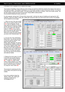
After a series of CAD iterations, the final concept for the aircraft combined an FDM centre body
(which contained the EDF units), wing end ribs, elevons and wing tips, with carbon fibre wing skins,
duck tail, intermediate ribs and access hatch. All FDM manufactured parts were made in ABS plastic
using the DPG’s Fortus 900 mc. All carbon parts apart from the intermediate ribs (which were laser
cut using the DPG’s Trumpf TruLaser 5030 Fiber) were manufactured using Vacuum Infusion. A two
part room temperature curing resin was used to eliminate the need for autoclave curing. This
strategy gave the advantage of direct from CAD manufacture of the EDF ducts, the geometry of
which is critical for efficiency. Form errors within the ducts which could result from conventional
manufacturing techniques were therefore eliminated. The less complex carbon fibre wing skins, tail
and hatch would have a smooth outer mould surface, light weight and high stiffness. Finished weight
of the aircraft was estimated at 3.5kg, with a projected cruise speed of around 20 m/s.
CAD image of the UAV.
The team mitigated the loss of RM techniques from the carbon fibre parts by trialling the use of FDM
printed moulds for their manufacture. This resulted in an enormous amount of experience being
gained into both mould design and composites manufacture. For economy, each mould was doublesided, and featured highly radiussed edges to reduce the risk of vacuum bag damage. The moulds
were made in ABS, sealed with acetone and hand finished to give a smooth surface.
Vacuum infusion of the top hatch using an FDM printed mould.
The manufacture of the carbon fibre parts using these moulds was successful, giving accurate parts
with a high quality surface finish.
Finished wing skin and its FDM mould
Centre Body
The centre body comprised an aerodynamic shell within which the propulsion and control gear was
located, along with the twin EDF ducts. These tubular ducts formed primary structural elements of
the body, enabling loads to be fed into their walls while giving a significant amount of longitudinal
stiffness. The body was a single printed part including complex internal features which could only
realistically be achieved with RM techniques.
FDM printed one-piece centre body.
Wing loads were transferred from the wings through tubular carbon stub spars bonded into sockets
printed within the body.
Carbon fibre stub spar for port wing.
The false trailing edge of the body incorporated clips for the duck tail to snap on to. The central area
of the upper surface of the body was open, giving clear access to the systems within. This opening
was covered with a carbon fibre access hatch incorporating NACA ducts and slotted air outlets
designed to cool the motor speed controllers and electronics. The hatch was recessed into the body,
and secured with countersunk fasteners which screwed into turned metallic inserts located in
printed bosses.
Top of centre body showing cooling vents for electronics.
Wings
The wings were designed to be removable. A hollow carbon spar was incorporated, which on
assembly slid over the stub spars protruding from the body. To ensure a smooth interface between
the wings and body, the printed inner wing ribs included a stepped edge around their periphery. This
step engaged with the body giving tight gap and flush tolerances. Wing fixing was achieved by
custom made carbon fibre bolts which passed through the spars into threaded inserts bonded inside
the centre body.
One of the aerodynamic modifications to the glider concept was the inclusion of more wing twist
(washout). This made wing manufacture more onerous, since any asymmetry would result in
difficulty trimming for level flight over the predicted speed range. To achieve accurate assembly, the
printed wing root and tip ribs, intermediate carbon ribs, and main spars were designed to self-jig to
the upper and lower skins. Structural adhesive was use to bond the parts together. Wing loads were
fed into the body stub spars through the ABS inner and carbon fibre intermediate ribs.
Wing structure with top skins ready for assembly.
Elevons were fitted to the wings, and were actuated by servos embedded into sockets printed within
the root ribs. Actuation was direct-drive through torque tubes which were a press-fit into the
elevons at one end, and into custom machined adapters mounted onto the servos at the opposite
end. There were no exposed parts, eliminating drag from the actuation system.
Starboard elevon with servo, adapter and torque tube.
Tail
The ‘duck tail’ at the rear of the body was added to the airframe to give more pitch trimming
capacity, and a degree of blown control due to its placement behind the EDF exhausts. The duck tail
comprised an FDM printed leading edge incorporating hinge sockets, and carbon fibre skins. All
components were designed for self-jigging assembly and were bonded together. The duck tail was
operated by a servo acting upon a carbon lever through a sliding yoke mechanism. The components
for this mechanism were all printed in ABS. Again, the entire actuation system was housed within
the body, thereby further reducing drag over a more conventional pushrod and horn system.
Duck-tail attachment points and lever.
Winglets
The printed winglets were retained on the wings using elastic bands to absorb landing shocks.
Previously, the tips were primed and subsequently painted fluorescent red to give improved visibility
in the air, however, the paint was highly prone to chipping. For the powered aircraft, red plastic was
used to build the wingtips thereby eliminating this issue and saving both weight, cost and
manufacturing time.
Starboard wingtip showing securing band and carbon wing securing bolt.
Catapult
Due to the increased weight and higher projected flying speeds of the powered version compared
with the glider, a catapult launch was deemed necessary. This was also designed in-house as part of
the project. The concept featured an automatic release mechanism which locked the UAV onto the
carriage, allowing the motors to run at full power before launch. Both the carriage and release
mechanism were built using FDM components. The launch speed target was 12m/sec, and this was
easily achieved, giving a peak acceleration of around 3g. The body required strengthening to
withstand these launch loads.
UAV ready for launch on catapult.
A small sprung panel was incorporated into the underside of the body to cover the launch hook
aperture during flight, giving a clean appearance.
Sprung door for catapult hook on underside of centre body.
Testing
Initial testing was performed with the aircraft tethered on a ‘zip wire’ on the DPG’s shop floor. The
aircraft was suspended from a line which stopped the aircraft from hitting the floor in the event of
loss of control. This gave a low-risk indication of the attitude the aircraft would have during the
critical seconds after leaving the catapult, and hence whether the calculated balance point was
within the limits required for manual control. It also gave an opportunity to test the catapult and the
operation of the FDM printed carriage and release mechanism. Kinematic analysis software was
used to ascertain the launch speeds attained using different catapult settings, thereby giving the
team confidence that the minimum flying speed was being attained.
UAV being prepared for zip-line testing.
After a series of successful tethered launches, testing progressed outdoors. The first launch was a
success, and the aircraft performed extremely well during its test flight.
Top cover removed showing internal systems.
Preparations for first test flight.
Kinematic analysis software was again used to gain flying speed data, which validated the initial CFD
analyses. Design Engineer John Mann commented:
“It was really interesting to get physical validation of the CFD work, showing that both the required
launch speed and the design cruise speed were correct. This will give the team confidence in the
modelling, and allow aerodynamic refinement in areas such as the duct shapes.”
UAV during first test flight.
Conclusions
Senior Design Engineer Dr. Garth Nicholson commented:
“The project was a success on all levels from team building, experience gained in structural and
systems design, design for manufacture through to testing and validation of CFD. The aircraft was
developed using both an incremental design philosophy, as well as trialling experimental
manufacturing techniques in carbon fibre production”.
Current work
Current developments include the investigation of vapour polishing for finishing printed ABS
components, particularly composite moulds, and the design and use of structural batteries.
The team is now looking forward to incorporating these developments, plus more sophisticated
electronic control systems and GPS into the airframe. The ultimate project goal is the design of a 3
metre span autonomous UAV, designed and built using advanced manufacturing techniques.
In flight, showing swept planform, raked wingtips and duck tail.
A video summary of the development and testing of the AMRC’s powered UAV prototype can be
found here:
https://www.youtube.com/watch?v=v4lrtOc736M
For detailed information about the development of the UAV, contact:
Dr Garth Nicholson, Senior Design Engineer.
g.nicholson@amrc.co.uk
For more information on the AMRC’s Design and Prototyping Group, contact:
Derek Boaler, Head of Design.
d.boaler@amrc.co.uk
© Copyright 2025
